Publication Information
ISSN 2691-8803
Frequency: Continuous
Format: PDF and HTML
Versions: Online (Open Access)
Year first Published: 2019
Language: English
| Journal Menu |
| Editorial Board |
| Reviewer Board |
| Articles |
| Open Access |
| Special Issue Proposals |
| Guidelines for Authors |
| Guidelines for Editors |
| Guidelines for Reviewers |
| Membership |
| Fee and Guidelines |
 |
Tracer Dilution Profiles for Mine Dewatering: Approach and Case Study
Michael Verreault1*, James T McCord2
1Hydro-Ressources Inc., Indio, California, USA
2Lynker Corp., Albuquerque, New Mexico, USA, jtmccord@lynker.com , ORCID 0000-0002-9394-7281
Received Date: May 20, 2024; Accepted Date: May 28, 2024; Published Date: July 23, 2024;
*Corresponding author: Michael Verreault, 1Hydro-Ressources Inc., Indio, California, USA, Email: mv@hydroressources.com
Citation: Verreault M, McCord JT (2024); Tracer Dilution Profiles for Mine Dewatering: Approach and Case Study, Enviro Sci Poll Res and Mang: ESPRM-147
DOI: 10.37722/ESPRAM.2024201
Abstract
In mine dewatering of fractured rock formations, identification of laterally extensive `water bearing discontinuities can be a key factor for many mining operations, providing opportunities to reduce inflows and/or optimize pumping well locations and extraction rates. Traditional field characterization methods, such as packer tests, slug tests, injection and air lift tests allow one to obtain some information about fractured rock aquifer properties. However, these approaches often are tainted with unquantified uncertainties and a scale effect. To address these challenges, a methodology has been developed and deployed, adapted from the traditional tracer point dilution method (PDM), to identify and characterize water bearing discontinuities in fractured rock.
As a result of method research, testing, and development, the PDM modifications employed for fractured rock formations utilize transient profiles of tracer concentration to identify the location of well-connected water bearing discontinuities with far better accuracy than traditional characterization methods. Most of the past applications of the PDM have been in shallow environments, and with low applicability on hard rock mining field conditions. This paper describes a field approach that utilizes tracer dilution profile (TDP) in holes up to 900 m deep and with a relatively short duration, to isolate water bearing discontinuities. When performed in multiple boreholes, the TDP tests can lead to a greatly improved understanding of the three-dimensional (3D) structures of well-connected water bearing features (e.g., faults and fracture zones) at a site. These tests identify water bearing discontinuities that exhibit significant flow under natural ambient conditions, while ignoring localized fracture zones and discontinuities that do not exhibit significant ambient flow.
In 2019 and 2020, this TDP method was applied to a mining dewatering project in Mexico. A total of nine boreholes were tested to isolate the connected water bearing features, and then locate pumping wells. The TDP method proved to be efficient, identifying and isolating several water bearing faults on the property. A 3D analysis of the TDP results allowed us to develop a structural model of the main important water bearing features. Complemented by the mine’s existing structural dataset and 3D mapping of features in the mine shaft and adits, the interpolation of some water bearing features between tested boreholes was proven accurate by the presence of visible faults mapped in mine openings. Based on the results of the TDP test program, two new pumping wells were drilled in an identified target zone, located within an underground drift at the target level. The two wells were each capable of supplying and maintaining 13245 L/min, for a total of 26495 L/min, inducing significantly more drawdown than the existing 11 dewatering wells had achieved.
Keywords: tracers, field characterization, mine, dewatering, fractured, ambient flow, dilution
Introduction
In mining operations, groundwater inflows often present a significant challenge, with failure to control inflows inducing downtime and expenses. In some mines, groundwater inflow is so problematic that operations may be compromised. In mining environments with fractured rock hydrogeology, it is critical to understand the well-connected permeable pathways, to optimise dewatering or water control strategy.
Most mining hydrogeologic field investigations focus on determining the formation hydraulic conductivity (K) and storage characteristics by inducing a stress to the flow system: either by extracting or injecting water. For example, slug tests are used extensively to obtain the “average” K value of a borehole drilled into open bedrock, and using the approach developed by Hvorslev (1951); but slug tests generally probe only very small volume of the formation and can be greatly impacted by the borehole condition and completion. Long-duration (24 hours or greater) pumping tests results can be interpreted using a variety of analytical methodologies (e.g., Theis, 1935; Cooper and Jacob, 1946) are utilized to determine larger-scale regional characteristics of rock aquifer, such as the transmissivity and the specific storage, as well as identification of potential hydrogeologic boundaries.
To isolate and test discrete, well-connected water bearing features, packer tests are widely used in diamond drill holes (DDH), typically interpreted using equations developed by Lugeon (1933). In complex multi-aquifer environments, some have utilized vertical flowmeter logging (Molz et al. 1989 and Paillet et al. 1987) describe such an approach to evaluate inter-aquifer flow in a borehole. Finally, air-lift tests remain an important characterisation methodology due to their easy application at low cost at discrete depth intervals as part of the borehole drilling process.
All these borehole field investigation techniques require the addition of a stress into the tested borehole to obtain useable results (apart from the vertical velocity logging in some specific circumstances). Depending on the volume of water in the applied stress, a scale effect impacts results and may lead to incorrect flow interpretation due to limited radius of influence or implicit duration of the testing method.
As an alternative to inferring K values via stress testing, Ogilvi (1958) suggested the Point Dilution Methodologies (PDM) to measure flow velocities in a borehole, and thus infer formation flow velocities. Others, such as Grisak et al. (1977), Chen (2001) and Jamin et al. (2015) pursued the development of the PDM with the use of packers. A disadvantage of the PDM with packers is that the process for a single flow measurement at a single depth interval is rather long and complicated, which limits its field applicability. More recently, a compact self-contained PDM unit with built-in “packers” has been deployed successfully at numerous sites (e.g., Osorno et al., 2018, Devlin, 2020). Termed the Point Velocity Probe (PVP), it similarly allows discrete measurements at selected depths applying the PDM and advection-dispersion principles but can be executed much more rapidly than a conventional PDM test with a double packer set-up.
In contrast to the point measurement methods, Pitrake et al. (2007) introduced the basic concept of utilizing snapshots of profiles of concentration of an artificial tracer in boreholes to infer flows and permeable zones. Maurice et al. (2011) carried out field testing to interpret ambient flow using profiles on shallow holes. The authors were using salt as a tracer and were measuring electrical conductivity to obtain their profiles of concentration. Finally, Collins and Bianchi (2020) developed an open-source code to interpret ambient flow measurement using profiles of concentration of an artificial tracer in open boreholes using salt as well. Based on our review, few if any have applied these methods to evaluate flow in fractured rock environments as applied to mining.
Method
A simple field approach was developed to locate hydraulically well-connected water bearing discontinuities (faults, fracture zones) that often control groundwater flow in bedrock mining environments. We term this approach the Tracer Dilution Profile (TDP) method. It consists of mixing a tracer into an open borehole and then measuring the evolution of the tracer concentration profiles over time. The main assumption is that observed decreases in tracer concentration over time at a given depth along a borehole is caused by ambient groundwater flow at that depth. An advantage of this test is that no stress need be applied to carry it out, and the ability to identify zones that flow under ambient conditions, overcoming the scale issues inherent in other borehole testing methods. In addition, groundwater trapped and stored in disconnected and poorly connected fractured “dead-end” zones are ignored because there is no significant ambient flow. The tests can be run in open boreholes, although we recommend installing a well screen to maintain the open borehole if there is danger of collapse.
In our case, we have utilized sodium fluorescein, a tracer in the family of the xanthene. Sodium fluorescein has been widely utilized for various configurations of tracer tests (Davis et al., 1985) and is proven to be non-toxic under a broad range of field conditions (Field et al. 1995). The tracer is mixed along the entire saturated portion of the borehole using a specifically designed apparatus built with a 3D printer. The tracer powder is compressed with 50% table salt by mass to form a solid puck that is inserted into the apparatus. The tracer puck is lowered into the borehole at constant velocity until the apparatus reaches the bottom of the borehole, and then it is brought back to surface at the same velocity, allowing slow and constant introduction of dilute tracer along the borehole. It is important to note that the tracer is not injected as a solution with water, to avoid imposing any hydraulic stress in the tested borehole and so maintain ambient flow conditions as closely as possible.
Once the tracer is completely mixed in the borehole (with a round trip of the apparatus with the tracer puck inside), measurement of concentration profiles is initiated. The profiles are measured using a commercially available optical fluorometer attached to a wireline. The profiles are carried out on an upward manner, i.e. from bottom to top of the borehole, to better ensure constant velocity on the probe and reduce the risk for the probe to hit a snag and/or temporarily block the borehole, which sometimes happens during probe lowering. The measured concentration is logged into a datalogger connected to the wireline and data are observed in real time on a computer connected to the datalogger. Figure 1 shows the spool holding the wireline, which in turn is connected to an external computer. Since the profiles of concentration are available in real time, it is possible to review the data in the field. This allows one to quickly determine the required time interval between each profile measurement and the number of profiles to be conducted to obtain sufficient information, with the goal to locate the main water bearing discontinuities. Sampling is done every second using the datalogger, connected to the optical fluorometer. The resulting variable is a voltage over time, that can be re-organised into a concentration versus depth. Therefore, due to the interpretation methodology, the value can be displayed in voltage versus depth, to avoid the need of a regression curve (voltage vs concentration) at each tested hole. The optical fluorometer utilized only provide values of low concentration, due to high accuracy, which mean that voltage above quenching of the fluorescein concentration would not be displayed.
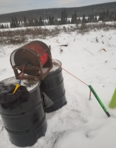
Figure 1: Illustration of the spool and the wireline holding the fluorometer.
Case Study – background, baseline conditions, and characterization strategy
Mine dewatering was required on a mining site located in the state of Chihuahua, Mexico. The mine is an underground operation ongoing since 2017: the host rock is composed mostly of limestone. Significant groundwater inflows required dewatering, and the water temperature provided a second motivation. With seepage zone groundwater temperature as high as 55 °C, dewatering also allowed better control over underground air temperatures, which can significantly affect worker safety and efficiency.
The ground elevation at site is around 1600 mamsl and the natural pre-mining piezometric elevation was around 1390 mamsl, nominally 210 m below the ground surface. In 2018, the total dewatering rate for the mine was of 18900 L/min, pumped from 11 conventional surface wells. Pumping these 11 wells caused an average drawdown of ~40 m (piezometric surface averaging 1350 mamsl). The life-of-mine plan delineated underground workings at final elevation of 1170 mamsl. Considering the current flow rate and piezometric level stabilized, it was estimated an additional flow of 85000 L/min would be required to dewater the lowest proposed mine workings. Since the piezometric surface had stabilized under the current pumping regime, yet an additional 180 m of drawdown was required to mine in dry and cooler conditions at the end of mine life, and the anticipated pumping rates were so excessive, the mine urgently needed a new approach to address their dewatering challenges.
To reduce overall cost, drilling pumping wells from underground drift was selected instead of drilling wells from surface. Drilling wells from surface was an expensive approach, given that approximately 250 m of unsaturated zone must be perforated before reaching the saturated zone. On top of this, the 430 m lift required, creating significant additional challenges and costs. The underground wells would discharge water into a sump, from which water would be discharged to the surface with centrifugal pumps, a much simpler and lower cost alternative to deep installations of high-capacity submersible or turbine pumps. The underground drilling rig had a maximum borehole diameter of 400 mm. To optimize the locations for the new dewatering wells, an accurate characterization approach was then required to isolate the targets. A total of 9 smaller diameter (100 mm) pilot holes (PH) were drilled from an underground drill bay, using a diamond drill rig: those pilot holes were to better locate the water bearing discontinuitites and to inform the best location to drill pumping wells from underground. Slotted pipes were installed to avoid in the holes to collapse. Figure 2 shows a 3D diagram of the mine layout and the distribution of the pilot holes. Since the piezometric surface was slightly below the drill bay, the pilot holes were not artesian, allowing us to carry various type of borehole tests, including TDPs.
Case Study – results
All TDP results were succesful allowing to locate multiple water bearing discontinuities. Also shown in Figure 2 is an example of a TDP test, in pilot hole No. 3. The figure also shows the locations of the water bearing intervals on a 3D diagram on each pilot holes tested.
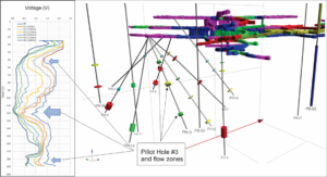
Figure 2: Illustration of the results in PH-3, and location of all the water bearing zones identified during the TDP testing campaign. Red cylinder indicates higher flow velocity and blue cylinder lower velocity.
As an example, the result in PH-3 shows 3 main water-bearing intervals, respectively at 50 m, 120 m and 185 m depths along the drill trace: the strongest water bearing feature is located at 120 m. Those 3 zones are draining most of the tracer from the borehole and are showing mostly horizontal flow, even with the mine under a dewatering stress. Seven concentration profile snapshots were sufficient to isolate the main flow zones along the drill trace, for a total duration of 99 minutes after tracer insertion. Since the medium is of high permeability and under stressed conditions due to active dewatering, the flow velocity was high, inducing tracer dilution in a short time periods. The initial profile was not perfectly uniform, showing that flow dilution had already occurred between the time of tracer insertion and the measurement of the first profile. This does not affect the quality of the results, since it is the changes in concentration over time that is the main factor impacting TDP interpretation.
To validate the quality of the results, a structural mapping campaign was performed on the galleries surrounding the drill bay. Two major faults were identified within the drift above the testing area. The structural data were compiled to project flat, planar extensions of the observed faults into the lower sections of the mine. These were identified to be significant water bearing features in agreement with flow observations derived from the TDP test results. Figure 3 shows one of those 2 faults with the location of the water bearing zones located using the TDP.
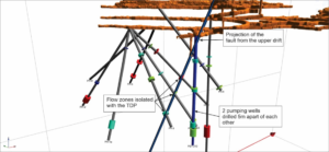
Figure 3: Illustration one of the two faults mapped in the upper drift and projected lower sections of the ore deposit. The fault is crossing the flow zones isolated with the TDP with good agreement. The pumping wells resulting from the final interpretation are also showed.
The position of the flow zones identified within the pilot holes 3, 6, 7 and 4 matches almost perfectly with the projection of the fault from the upper drift, illustrating the accuracy of the methodology. Based on those results, multiple faults were drawn to generate a 3D model of the water bearing features, while ignoring localized disconnected water bearing discontinuities. From this information, two wells were drilled from the drift targeting the identified faults. Each was tested and commissioned to a flow rate of 13245 L/min, for a total flow rate of 26490 L/min, which is higher than the combined capacity of the 11 existing surface dewatering wells. Over the recent years since installation of the new dewatering wells, the yield has been maintained and dewatering levels have dropped well below the previous steady groundwater elevations.
Conclusions and Next Steps
Traditional hydrogeologic characterization methods utilized for mine dewatering focus on defining permeability and storage characteristics of formations to be dewatered. In fractured rock formations, it is critical to identify highly connected water bearing features. The TDP method allows one to isolate those water bearing discontinuities with accuracy relatively quickly at low cost compared to traditional characterization methods. A case study illustrates the efficacy of the method, including verifying the TDP-identified flow zones as coincident with mapped geologic faults, allowing the citing of two dewatering wells capable of sustaining high flow rates.
Some challenges remain when TDP tests are applied to extreme low permeability formations where diffusion appear to be of some importance. Interpretation may also be more complicated in boreholes with high vertical flow intervals. We continue to apply the TDP method at other mine sites across the world and are currently benchmarking the method against PVP measurements as an independent verification of the method (Guerra et al, 2024).
Acknowledgements: The authors want to thank MM Alain Verreault and Thierno Bah for the field tests performed on this site of Mexico.
References
- Chen J (2001) Study of Fissured-rock Seepage Flow with Isotope Tracer Method in Single Borehole. Science in China 44: 109-113.
- Collins S, Bianchi M (2020) DISOLV: A Python Package for the Interpretation of Borehole Dilution Tests. Groundwater 58: 805-812.
- Cooper HH, Jacon C.E. (1946) A Generalized Graphical Method for Evaluating Formation Constants and Summarizing Well Field History. Am. Geophysics 27: 526-534
- Davis SN, Campbell D.J., Bentley H.W., Flynn T.J. (1985) Ground Water Tracers. National Water Wells Association 1-200
- Devlin, JF, 2020. The Groundwater Project: Groundwater Velocity, ISBN 978-1-77470-000-6
- Field MS, Wilhelm R.G., Quinlan J.F., Aley T.J. (1995) An Assessment of the Potential Adverse Properties of Fluorescent Tracer Dyes used for Groundwater Tracing. Environmental Monitoring and Assessment 38: 75-96
- Grisak GE, Merritt W.F., Williams D.W. (1977) A Fluoride Borehole Dilution Apparatus for Groundwater Velocity Measurements. Canadian Geotechnical Journal 14: 554-561.
- Guerra, PA, M. Verrault, J.T. McCord, and J.A. Clark, 2024. Application and Comparison of Borehole Tracer Methods for Mine Site Hydrogeologic Characterization, in preparation for Mine Water and the Environment, Journal of the International Mine Water Association (IMWA).
- Hvorslev MJ (1951) Time Lag and Soil Permeability in Ground-Water Observations. Wayterways Exper. Sta Corps of Enginneers, U.S. Army, 36: 1-50.
- Jamin P, Goderniaux P, Bour O, Le Borgne T, Englert A, Longuevergne L, Brouyere S (2015) Contribution of the Finite Volume Point Dilution Method for Measurement of Groundwater Fluxes in a Fractured Aquifer. Journal of Contaminant Hydrology 182: 244-255
- Kass W (1998) Tracing Technique in Geohydrology. A. Balkema, Rotterdam, 581p.
- Lugeon M (1933) Barrage et Geologie. Dunob, Paris.
- Maurice L, Barker J.A., Atkinson T.C., Williams A.T., Smart P.L. (2011) A tracer Methodology for Identifying Ambient Flows in Boreholes. Groundwater 49: 227-238.
- Molz FJ, Morin R.H., Hess A.E., Melville J.G., Guven O. (1989) The Impeller Meter for Measuring Aquifer Permeability Variations – Evaluations and Comparisons with other Tests. Water Resources Research 25: 1677-1683
- Ogilvi NA (1958) Electrolytic Method for the Determination of the Groundwater Filtration Velocity (in Russian). Bulletin of Science and Technology News 4.
- Osorno, T, Firdous, R., Devlin, J.F. 2018. An in-well point velocity probe for the rapid characterization of groundwater velocity at the centimeter-scale. Journal of Hydrology, v. 557, 539-546.
- Paillet FL, Hess AE, Cheng CH Hardin E (1987) Characterization of Fracture Permeability with High-Resolution Vertical Flow Measurements during Borehole Pumping. Groundwater 25: 28-40
- Pitrake M, Mares S, Kobr M (2007) A Simple Borehole Dilution Technique in Measuring Horizontal Ground Water Flow. Groundwater 45: 89-92.
- Theis CV (1935) The Relation Between the Lowering of the Piezometric Surface and the Rate and Duration of Discharge of a Well using Groundwater Storage. Am Geophys Union Trans 16: 519-524