Publication Information
Frequency: Continuous
Format: PDF and HTML
Versions: Online (Open Access)
Year first Published: 2019
Language: English
| Journal Menu |
| Editorial Board |
| Reviewer Board |
| Articles |
| Open Access |
| Special Issue Proposals |
| Guidelines for Authors |
| Guidelines for Editors |
| Guidelines for Reviewers |
| Membership |
| Fee and Guidelines |
 |
Basic Principles of Conventional and Laser Driven Therapy Accelerators
Scarlat Florea1, 2*, E. Badita2, E. Stancu2, 3, A. Scarisoreanu2
1Valahia University of Targoviste: Bd. Carol Street/2, Targoviste, Dambovita, Romania
2National Institute for Laser, Plasma and Radiation Physics, Atomistilor Street/409, Magurele, Ilfov, Romania
3University of Bucharest, Faculty of Physics, Atomistilor Street/407, Bucharest, Romania
Received Date: October 28, 2019; Accepted Date: November 07, 2019; Published Date: November 18, 2019
*Corresponding author: Scarlat Florea, Valahia University of Targoviste: Bd. Carol Street/2, Targoviste, Dambovita and National Institute for Laser, Plasma and Radiation Physics, Atomistilor Str. /409, Magurele, Ilfov, Romania; Email: scarlat.f@gmail.com
Citation: Scarlat F, Badita E, Stancu E, Scarisoreanu A (2019) Basic Principles of Conventional and Laser Driven Therapy Accelerators. Advances in Medical Imaging and Health Informatics Vol 2019 Issue 1: pg 1-23.
Abstract
Radiation therapy with external radiation of a malignant tumor located in a patient’s body requires that the radiation beams meet two conditions: 1) – they have sufficient energy to penetrate to the depth of the tumor, regardless of its location, and 2) the radiation intensity is uniform on the irradiation field at the entrance to the tumor to provide the energy absorbed in the mass of 2 Gy per irradiation fraction. These beams are provided by special equipment that in their component has a charged particle accelerator. Accelerated particles can be extracted, directly to the desired energy as corpuscular radiation or directed on a metal target to generate bremsstrahlung radiation. Then, these beams are processed to obtain the distribution of absorbed doses for the type of tumor. At present, the light particles (electrons and photons) are generated by betatron, linac, microtron, and synchrotron and heavy particle beams (protons and ions of another atom) are generated by cyclotron, synchrocyclotron, isochronous cyclotron, and proton synchrotron. The hydrotherapy accelerators compared to the electron accelerators have a number of disadvantages, of which two are mentioned: the low acceleration gradient of 1 MeV/m which leads to the lengths of the acceleration trajectory of the order of 600 m, the installation surface of 2000 m2 and the small value of the magnetic field B < 2T which leads to weights of about 1000 tons. Using superconducting magnet technology (B <10T) the weight of the accelerator is reduced to 20 tons for protons and to 600 t for protons and carbon ions. These disadvantages explain the low number of 30, compared to that of the electron accelerators 5000 and of those do not allow widespread medical use. These disadvantages can be overcome by replacing the conventional radiofrequency technology with the laser technology in relativistic mode that allows electric fields of acceleration of 1 TV/m and magnetic fields of 102 MG.
Following the presentation of the principles of electrostatic and electromagnetic acceleration, of the resonant and non-resonant principles using RF technology, the paper presents the acceleration principles driven by laser in vacuum, plasma and solid to obtain the clinical energies of 50 – 250 MeV for protons and 100 – 450 MeV/u for carbon ions.
Introduction
The basic idea of acceleration involves the existence of two entities: the electric field and the charged particle that represent interest for a certain application, for example – radiotherapy in the case of this work. The local electric field applied by the associated electric force produces the acceleration of charged particles, introduced or in the field when applied. The kinetic energy gain is equal to the product between the beam charge and the electrostatic field potential.
The acceleration field is characterized by electric force lines, which coincide with the path (trajectory) of the charged particle, according to the law of electromagnetic induction. In this field representation, the tangent at any point of the field line indicates the direction of the electric field vector at that point.
The acceleration field is characterized by electric force lines, which coincide with the path (trajectory) of the charged particle, according to the law of electromagnetic induction. In this field representation, the tangent at any point of the field line indicates the direction of the electric field vector at that point.
The linear or circular acceleration of a charged particle in any field is done by transferring energy from the field to the particle. In the electrostatic field the acceleration is direct and non-resonant.
In order to exist energy transfer, in linear acceleration or circular acceleration, the particle must meet the periodic electric field wave at the same phase, in other words the particle must be synchronized with the wave.
In the paper, as schemes associated with the principle of electrostatic acceleration, we mention: Cokcroft – Walton acceleration, based on DC voltage supply, Van de Graaff acceleration based on the concept of electric charge transport and Tandem Van de Graaff acceleration for ion based on a single DC voltage generator.
In the category of unreasonable acceleration, the principle of acceleration of electrons by induction, called in the work the principle of betatron acceleration, enters. As with all principles, the name of the principle was given by the name of the device associated with the acceleration method, in this case “betatron”.
At circular acceleration, we have two frequencies: the rotation frequency of the particle in the circular orbit, which depends on the ratio of the magnetic field to the particle mass and the frequency of the RF voltage that depends on the external RF generator. The resonance occurs at the equalization of these two frequencies.
At resonance, when the magnetic field and particle mass remain constant, we have the principle of cyclotron acceleration. When the energy of the accelerated particle exceeds a certain value, the mass begins to increase and the resonance disappears.
Resonance maintaining can be done by decreasing the frequency of the RF generator synchronous with increasing the particle mass. In this case, we have the first version of the cyclotron, the synchrocyclotron acceleration.
The second version that maintains resonance consists in increasing the magnetic field synchronous with the increase of the particle mass. This version is called isochronous cyclotron acceleration. The principle of linear acceleration being resonant, the lack of the magnetic field simplifies the dynamics of the problems.
In order not to leave the linear or circular trajectory during the acceleration period, the charged particle needs focusing forces in the transverse plane and in the longitudinal direction. These requirements determined the appearance of the weak focus principle, the principle of edge focus, the principle of intense focus and the principle of phase stability. All of these focusing principles led to the Synchrotron acceleration principle.
Synchrotron acceleration uses the magnetic field only in the area of equilibrium orbit. This idea was applied to acceleration in the Fixed Field Alternating Gradient (FFAG) radial and sector type.
All the acceleration principles mentioned above are based on radiofrequency technology, in the sense that the accelerated particles gain energy from the RF electric field [1-12]. The development of laser technology by constructing laser systems with powers over 10 PW (1PW = 1015 W) and electric fields with 3-4 orders of magnitude compared to those of RF, made it exist as an alternative for acceleration, laser radiation fields [13- 17]. The paper presents the principles of acceleration based on both technologies.
Basic Parameters of Acceleration
Radiation Therapy Particles of Interest
These can be elementary or compound. An elementary particle meets the criterion that its size “d” be smaller than any measurable dimension, i.e. reduced Compton wavelength ƛC ≡ λC / 2π = ℏ / m0 c.
The electron, the elementary particle, has d/ƛc< 1×10⁻⁵. The composite particles have the ratio d/λc, as follows: proton and neutron ≈ 9.6, pion ≈ 1.4 and atom (12C) ≈ 3.2×10+7. We noted ℏ ≡ h/2π = 1.055×10⁻³⁴ Js -the reduced Planck constant, m0 – the particle rest mass, and c – the speed of light in vacuum.
Particle
Factor, Ԛ
Mass, m0 / amu
Life-time
Photon – boson
0
–
–
Electron – fermion
-1
m0=0.511 MeV
stable
Pion – meson
-1
273 m0
2.10-8 s
Neutron – baryon
0
1838 m0
12 min
Proton
+1
1836 m0
stable
Alfa
+2
4 amu
stable
C-ion
+6
12 amu
stable
Ne-ion
+10
20 amu
stable
Ar-ion
+18
40 amu
stable
Heavy particles in the nucleus called hadrons are of two types: baryons (composed of three quarks, spin ½) and mesons (composed of quark and antiquark, spin 0).
Some characteristics of the particles of radiotherapeutics interest are presented above in (Table 1). In this paper, we will refer to photons, electrons, protons and carbon ions, currently used in radiation therapy. Linear electron accelerators have high performance regarding energy to reach any point of tumor localization, as well as intensity to administer the radiation dose of 2 Gy per irradiation fraction corresponding to the irradiation with photon and electron beams. The main clinical requirements for proton and carbon ion therapy are presented in Table 2.
Parameter
Value
Units
Extraction energy (proton) (m,M)
50, 250
MeV
Extraction energy (carbon) (m,M)
100,450
MeV/u
Energy step (proton) (at M, at M)
5,1
MeV
Energy step (carbon) (at m, at M)
15,6
MeV/u
Energy resolution ∆E/E (at m, at M)
3.5,1.8
–
Voxel size (m, M)
4×4,10x10x10
mm
Smallest field of view (m, M)
10×10, 25×25
cm
Clinical dose rate (protons) (m, M)
2, >10
Gy/min
Clinical dose rate (carbon) (m, M)
2, >10
Gy/min
Cycle rate
0.5, 2
kHz
Bunch charge (proton) (m, M)
1.6, 16
pC
Bunch charge (carbon) (m, M)
300,3000
fC
Effective Source – Axis Distance
>3
m
Particle Energy
Particle energy is obtained from the relativistic factor γ = (1-β2)-1/2. It can also be written as a dispersion relation for the particle γ2 = β2γ2 + 1, or in shape E2 = (pc)2 + E02. Here the total energy E (=T+E0) is the sum between kinetic energy T and the rest energy E0, E0 = m0c2, E = γm0c2, and impulse p = βγm0c, pc = βE, β = v/c.
In the case of a particle with the charge q = Qe and the atomic mass A, normalized to the mass of the atomic unit mu, we have: E2 = p2c2 + A muc2, where A ≡ (m0/mu), E0 = m0c2 = Amuc2 = AEu, E = γAmuc2, T = Amuc2 (γ – 1) and Eu = 931.5MeV/c2, u is the atomic mass unit (amu).
Beam Intensity
Denoting by C – the accelerator circumference, N – the number of particles and fr = c/C, – the revolution frequency, the average current Iav, is given by the relationship Iav = N·q·fr
For proton irradiation the average beam intensity on the target is Iav = 1nA and the kinetic energy T = 50-250 MeV. At proton energy of 100 MeV, the irradiation time t=1min, and the tumor mass m= 1kg= 1000 cm3=1L, the absorbed dose in tumor is D= T.Iav.t/m= 6Gy. For a transfer efficiency η = 1/3 we have a dose of 2Gyper liter (L) and per minute (min).
For photon irradiation the absorbed dose in the tumor is D[Gy/min] = 9.61×10⁻⁹·Φ[γ/cm2s]·E[MeV/γ] ·(μen/ρ)m [cm2/g], where Φ is fluency rate, E – photon energy and μen/ρ – the mass energy attenuation coefficient for medium m.
For electron irradiation, the dose is given by D [Gy/min] = 6×10⁴·δ [nA/cm2]·S[MeV·cm2/g], where δ is the current density and S is the mass stopping power which depend of the particle energy. The dose rate of 2Gy/min correspond to a density of 15 pA/cm2, ICRU 35.
Nonresonant Acceleration Principles
Acceleration in Electrostatic Field
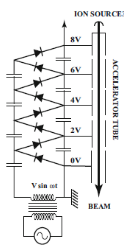
Direct acceleration is a method by which charged particles q, produced by a source called injector, are driven by an assembly of electrodes – acceleration tubes – so as to cross a difference of electrical potential ∆V called voltage U, taking over from at the electrostatic field a kinetic energy
![]()
where ε = dV/ds is the gradient of the scalar electric potential and d the length of the field.
The acceleration tube may consist of several electrodes and in this case the voltage is properly divided between them to constitute acceleration intervals (Figure 1a) or the tube is with uniform field, consisting of a sequence of identical diaphragms separated by ceramic insulating rings (Figure 1b).
(a)
 (b)
(b)
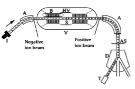
Figure 1: Schematic layout of the rectifier circuit used by Cockroft and Walton accelerator for to generation the high DC voltage [10]; b. Schematic design of a Tandem Van de Graaff accelerator: I-negative ion source, injector, A – analyzing magnet, B – belt generator, HV – high voltage, S stripper foil or gas, and V – high pressure vessel [18].
The acceleration is direct and linear if the terminals of the high-voltage generator are connected to the ends of the acceleration tube (Figure 1a).
In the field of electrostatic acceleration there are three types of acceleration that use continuous voltage: Cockroft-Walton at which the high voltage is obtained by rectifying the alternative voltage, Van de Graaff applying the concept of “load transport” and Tandem Van de Graaff, single or two step by step, see (Figure1b) [18].
J. Cockroft and E. T. S. Walton made in 1932 an 800 keV cascade generator to accelerate protons [19]. For the initiation of the first artificial atomic reaction: p+ → α + α, they received the Nobel Prize in 1951.
In 1931, R. J. Van de Graaff, to significantly increase the potential difference, introduced the concept of charge transport and built the first accelerator, which bears his name [20].
The doubling or multiplication of the ion energy in tandem, based on the principle inversion of the ion charge by stripper foil (H- → H +) is conceives by L.W. Alvarez in 1951 [21]. Acceleration starts for negative ions and then for positive ions using a single high voltage generator.
Induction Acceleration Principle
The principle of betatron acceleration is based on the time variation of the magnetic field with axial symmetry, for the induction of an electric field of acceleration at the level of equilibrium orbit, according to the law of electromagnetic induction.
The acceleration path can be circular or linear. The acceleration of the electrons is nonresonant.
The idea of electron acceleration along the induced electric field line was presented by J. P. Slepian in the patent entitled “X Ray Tube” (Figure 2) [22-23].
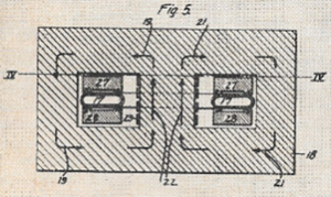
Figure 2: J. Slepian, “X Ray Tube”, US Patent No 1,645,304, Filed April 1, 1922, Granted Oct. 11, 1927 [22].
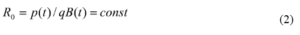
The magnetic force, in balance with the centrifugal force, (mv2 / Ro) + q (vxB) = 0, ensures the movement of the electron on a circular path of constant radius
based on self-synchronization of p(t) with B(t).
The electron load being negative, it rotates counter-clockwise around the magnetic field (Figure 3).
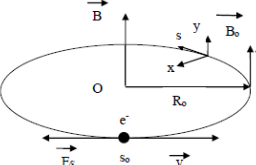
Figure 3: Principle of betatron acceleration.
The kinetic energy of the accelerated electrons in the betatron is deduced from the energy-impulse relation, as follows:
where R0 is the radius of equilibrium orbit and B is the value of the magnetic field at the radius of equilibrium orbit. Under the radical we have the square of the rest energy of the electron (E0 = m0c2 = 0.511 MeV) and the square of the product between the energy equivalent (c·e = 299.8 MeV / Tm) of the magnetic rigidity of the electron beam of charge e on equilibrium orbit and magnetic rigidity (BR0 [Tm]).
Electron charge is q ≡ eQ, where Q is the charge multiplication factor: Q = -1 and e ≡ |e| = 1.6022×10⁻¹⁹ A·s = 4.8×10⁻¹⁰esu (≡ Fr = 1.0622×10⁻²⁰ Bi.s; 1Bi ≡ emu =10 A = 3×10¹⁰esu) and c = 299.792.458 m/s exactly by definition of the meter ≈ 2.998×10⁸ m/s.
The magnetic field at the radius of the circular orbit is half of the average magnetic field between the center and the equilibrium orbit, B (R0) = Bm / 2. This is called the ½ condition of Wideroe (1928 [24]).
The electron oscillations around the equilibrium orbit, (called the betatron oscillations), are stable when the magnetic field index in the acceleration zone, n (≡ – (r / B). (dB / dr)), has values between zero and unit, 0 <n <1. This condition, called the weak stability principle, was established by Steenbek (1935, [25]).
The first betatron was built by Kerst in 1940 [26]. Then followed the construction of several other companies (Alis Chalmers, Siemens, Brown Boveri, Toshiba), with energy between 5 MeV and 45 MeV. The highest energy was 340 MeV, B = 0.92T, R0 = 1.22 m (Kerst, 1949).
The first proposal for the use of braking radiation generated by betatron in radiotherapy was in 1948. In 1967 there were 137 medical betatrons with energy between 15 and 45 MeV [27]. In Romania, the first irradiation on patients with malignant tumors began on October 20, 1970, with the braking radiation of 30 MeV generated by the IFA Betatron of 30 MeV [28-35].
The maximum energy limit of the betatron was imposed by the synchrotron radiation.
Synchrotron radiation is generated by the movement of the electron on a circumference due to centripetal acceleration, dv/dt = (1 / mγ) dp/ dt, normal on acceleration parallel to the electron’s movement in equilibrium orbit, dv/dt = (1/mγ3) dp/dt [36-37].
The total energy radiated by the electron in the unit of time per rotation, i.e. the power P in W, is proportional to the fourth power of the electron energy and inversely proportional to the fourth of the electron (or positron) rest mass.
![]()
where α = e2/4πε0ℏc ≈ 1/137 represents the fine structure constant and R0[cm]– radius of equilibrium orbit, c is the speed of light in vacuum, β = v/c is the speed of particle normalized to speed light.
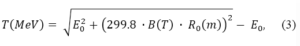
In the rest frame of the electron, for low speeds (β << 1) the radiation distribution is concentrated in the transverse plane (x, y), i.e. dP/dΩ ≈ sin2 θ, where θ is the angle between the direction of centripetal acceleration and the direction of observation. The maximum radiation intensity is located in the perpendicular direction to the plane of rotation of the electron.
In the case of the relativistic electron (β ≈ 1), to obtain the angular distribution in the laboratory system, Lorentz transformation between the angles of observation in the two reference frames is applied, sin θL = sin θr / γ (1 + β cos θr).
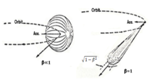
Figure 4: Synchrotron radiation angular distribution for non and relativistic electrons on a stabile circular orbit [38].
At the observation angle θr = 900, it results that the power of synchrotron radiation is emitted within an angle θL = 1 / γ in the direction of the particle propagation (Figure 4). The duration of the synchrotron radiation pulse detected by a stationary observer, in the system attached to the electron, is ∆tr ≈ ρ / γc.
The transformation in the laboratory system introduces the relativistic factor 1 / γ2, so that ∆tℓ ≈ ρ / γ3c. For values, e.g., γ = 54×103 and ρ = 580 m, the flash takes ∆tℓ ≈ 1.23×10⁻²⁰ s. The duration of this short pulse will contain, according to Fourier synthesis, a spectrum of harmonics of the revolution frequency up to ω ≈ (∆tℓ)-1 = γ3c/ρ = 0.8×10²⁰ Hz, which corresponds to the photon energy ℇ = ℏω ≈ 53.6 keV or wavelength λ ≈ 2.2 nm. The lost the synchrotron radiation energy is ∆E = 80 MeV.
Acceleration in radiofrequency field
Principle of Linear Acceleration
The principle of linear acceleration consists in the acceleration of charged particles in a straight line in areas with RF electric field separated by areas without field, repeated n times up to the established energy. The resonance condition is ensured by meeting the particle with the electric field of acceleration at the same phase in each acceleration interval.
Field areas can be located between two cylindrical metal tubes or inside an RF cavity. The condition of resonance or synchronism in the case of RF supply (ω = 2π / T, k = 2π / λ) for multicellular cavity is L = vT / 2 = βλRF / 2, where v = βc is particle velocity and T-RF period. It can be seen that the synchronism for the length of a cell depends on the speed of the particle.
Until the advent of the modern 3 GHz linac, a series of acceleration configurations were proposed, of which we mention: resonance acceleration with drift tubes, made by G. Ising (1925), acceleration with stationary wave – Wideroe 1928, successfully tested in 1931 by to D.H. Sloan and E.O. Lawrence (30 tubes, 42 kV at 10 MHz, 10-7 A, beam of 1.26 MeV single charged mercury ions) And the construction of the 32 MeV linear proton accelerator (Injector: Van de Graaff of 4 MeV), Iave = 4×10⁻⁹ A, Ipeak = 1μA, beam diameter of 3 mm, 202 MHz) in 1955 by L. W. Alvarez and co-workers [39].
Modern proton linear accelerators are based on the Alvarez Drift-Tube Linac. Alvarez was awarded the 1968 Nobel Prize in Physics for his contributions to elementary particle physics.
In the case of a linac, the acceleration is based on the energy transfer from the RF field, generated by a microwave source of type magnetron or klystron (3-5.7MHz) to an electron beam, at their interaction in a microwave resonant cavity [40-42].
The general shape of the dispersion diagram (k = f (kz)) for the TEM electromagnetic transverse wave and the degenerate modes (magnetic transverse TM and transverse electric TE) in free space are shown in Figure 5. Photons being quanta of EM radiation means that classical EM waves consist of large numbers of coherent photons.
Figure 5: The general form of the dispersion relation for the modes: TM, TE and TEM. TM and TE modes are degenerate.
The TM wave is used for acceleration because the electrical component of acceleration is on the axis of the cavity. Kapcinski and Teplyakov, starting from the idea of using the TE wave for acceleration, invented the device associated with the acceleration method called “Linear ion accelerator spatially homogeneous strong focusing” in 1970 [43].
To accelerate the particles in the cylindrical waveguide, the TMrθz mode (Ez ≠ 0, Hz = 0) is chosen. The acceleration field Ez in cylindrical coordinates (r, θ, z) is

where r is the position vector, m is order of the Bessel’s functions. The factor kc = (k2 – kz2)1/2 is the cut-off wave vector which separates far fields from near fields.
The solution of equation (5) is given by the Bessel functions in the form Ez = E0Jm(kc,r) exp i(ωt-mθ-kzz). For the lowest order m=o, (Ez,r,t) = E0 J0(kc r) exp i(kzz –ωt), and the boundary condition: Ez = 0 for r = a – the radius of cylindrical waveguide, the first root a1 is at kc.a1 =2.405, and the field configuration is shown in (Figure 6).
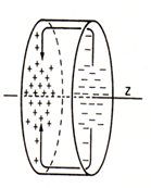
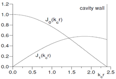 Figure 6: Cylindrical Resonant Cavity for linear accelerator. Electromagnetic field pattern for a TM010 -mode in a circular waveguide
Note that TMrθz solutions are characterized by three indices: r and θ indicate the number of half waves for the electric field in the radial and azimuthal coordinates and z denotes the number of half waves for the electric field in the longitudinal direction.
Figure 6a represents the three-dimensional configuration of the field in the cylindrical cavity and Figure 6b – the radial distribution of the field in the cavity. It was observed that the Besel functions best approximate the real field, because on the axis of the cavity, the electric acceleration field has the maximum value and the magnetic field the value zero.
In the case of empty cavity, kc is real and finite, the wave equations represent far fields k0 > kz, k0 > kc,. Phase velocity of the wave in z direction, vph≡ ω/kz, given by relation
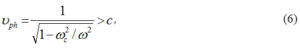
exceeds the speed of light in vacuum and the wave cannot be used to accelerate real charge.
To be useful for accelerating charges, the fast wave is transformed into a slow wave by using a cylindrical waveguide loaded with discs provided with iris [Figure 7].
Figure 7: Disc loaded cylindrical waveguide.
In this case the phase speed of the slow wave is
![]()
and we can find a n such that vph is equal to the velocity of the particles, which is the condition for acceleration. In this case, the beam takes energy from the field or the beam acts as a positive resistive load for the field.
For linacs with traveling wave to the energies used in radiotherapy, microwaves with frequencies of 3000 MHz are used, the frequency of repetition of the pulses of 10-100 Hz and the duration of the macropulses of about 2-6 μs. The field gradient is about 10-15 MV / m. For linacs with stationary wave and radio frequency cavities, the frequency is 100-3000 MHz.
Phase stability in linear acceleration is simpler because the magnetic field is missing. The length of the trajectory between two consecutive passes through the acceleration interval is fixed by construction and the value of the particle pulse does not influence this length. The synchronous phase is stable and has a negative value. There is no transition energy.
In the linear acceleration there is an auto phasing, both at the progressive and at the stationary wave (Figure 8). The particle initially starts from a smaller phase than the synchronous phase. After a number of passes the phase becomes equal to the synchronous phase but with less accumulated energy than that of the synchronous phase. The phase shift continues until the energies become equal. At this point, the displacements begin to take place in smaller phases and the synchronous particle phase oscillates around the synchronous phase.
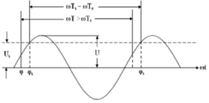
Figure 8: Auto phasing in linear acceleration.
The formula for kinetic energy gain in the gap is
where: V0 =E0L is the voltage gain of a particle if the gap voltage was fixed in time at its maximum value,
T(β) is the transit time factor accounts for time of the variation field while particle moves through gap [-g/2; g/2].
and the cos φs accounts for actual phase of the field when the particle arrives at the electrical gap and Φ=ωt is the phase of the field when particle is at the center of the cell (t =z =0). When Φ=0 (t=0), the field is maximum. Ez = Ez0cos Φ.
Time structure of a pulsed linac beam consists in a string of micropulses within macropulses. In conventional RF linacs, the micropulse time is τm ≈ 10 ps and the macropulse time is TM ≈ 4μs. The micro-pulse and macropulse repetition rate is typically fm ≈ 3-5.7 GHz and fM ≈ 100-200 Hz, respectively. The separation of micropulse is ∆Tm = 1/fm ≈ 350 ps and the overall duty factor for the full electron pulse train is DF = fMfmTMτm.
The average beam current is obtained from the relationship Pave = Iave.·V. In this relation, V is accelerating potential for the electron beam and Pave is the average beam power. The average power is derived from the duty factor DF and peak power, Pave = (DF)·Ppeak. The electron beam terminal voltage V is readily obtained from the beam energy E and electron charge q·V = E/q. This value determines the average beam current Iave= Pave/V = (DF) Ipeak.
Depending on the accelerated beam current, (Figure 9), shows the efficiency, braking radiation and kinetic energy of the electrons for the two types of accelerating waves: progressive and stationary waves [44-49].
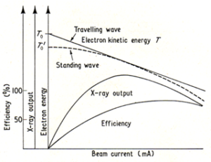
Figure 9: Variation of electron beam energy, efficiency and X-ray output vs beam current in linac [50].
Under equilibrium electronic conditions, at irradiation with photons with energy E up to 3 MeV, the radiation intensity I required to obtain a dose of 1 R / min is I[MeV/cm2.s] = 9.1×10⁵/ (μen/ρ) where (μen/ρ) [cm2/ g] is the mass energy absorption coefficient and ρ is the density of medium. When photons have energy over 3 MeV, Kerma K[Gy] = 1.6022×10⁻¹⁰ Φ. (μen/ ρ) m.Ehω / (1-g), g being the energy fraction lost to radiative processes.
For linac energy limitations are given by the length of the accelerator which in turn is determined by the gradient of the RF electric field for acceleration. Linacs are capable of delivering beams with high energy, high intensity and good beam quality (small emittance).
Linac-based radiation therapy for cancer treatment began with the first patient treated in 1953 in London, UK, at the Hammersmith Hospital, with an 8 MV machine built by Metropolitan-Vickers and installed in 1952, as the first dedicated medical linac. A short while later in 1954, a 6 MV linac was installed in Stanford, USA, which began treatments in 1956 [51].
The schemes for the forming of radiation beams for therapy are shown in (Figure 10).
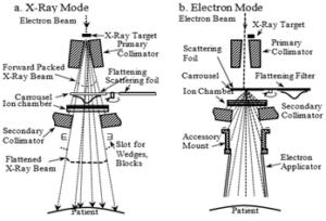
Figure 10: Schematic cutaway diagram of typical treatment head for a high energy bent beam medical linear accelerator: a. X-ray therapy mode, and b. Electron beam therapy mode [52].
With minor modifications, they are used in both linear and circular accelerators. Corresponding to the two modes of operation above, the distributions of the absorbed doses on the axis of the radiation beam in depth (in cm) are shown in (Figure 11).
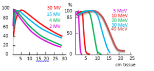 Figure 11: Absorbed dose distributions on the axis radiation beams at SSD = 100 cm and fields of (10×10) cm for a) X-ray beam of 2 MV – 30 MV and b) electron beams of 5 MeV – 40 MeV.
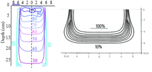
Figure 12: Isodose distributions, for example, a. 8 MeV X rays and b. 12 MeV electron beam.
For use in radiotherapy, the energies between 4-25 MeV for electrons and the same energy range for braking radiation are used. Braking radiation is generated by electron interaction with a solid target. In 1967, 106 linear medical accelerators in the energy range 2-35 MeV was in operation [27].
The isodose curves raised in a water phantom (tissue equivalent), used for the elaboration of a patient’s treatment plan are shown in (Figure 12). The isodoses are indicated in percentages and the depth with respect to the phantom’s entry surface in centimeters.
The basic principle of the elaboration of the treatment plan is to ensure a dose of 100% at each point in the volume of the irradiated tumor, i.e. 2 Gy per irradiation fraction.
Regarding linacs for proton and carbon ion therapy, we mention the linac – based complexes for hadron therapy in design (D), testing (T) and operation (O) at the level of 2011 [53]: LIBO (LInearBOoster)(T), linac, SCL 3GHz, p:62-200 MeV,400Hz,13.5 m, Inj.: cyclotron; IDRA, a cyclinac-based facility for proton therapy, the concept of cyclinac (a cyclotron followed by a linac) was proposed by U. Amaldi in 1993 and developed by TERA Foundation, IDRA (D), linac, SCL 3GHz, p: 30-230 MeV, 100-200Hz, 18m, Inj.: cyclotron;
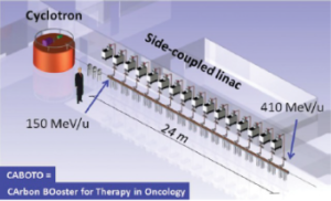
Figure 13: The CABOTO design. Only cyclotron and linac in the figure [54].
CABOTO (Carbon BOoster for Therapy in Oncology) (D), linac (LINear Accelerator for Clinical use), SCL 3 GHz, C: 300-430 MeV, ≤ 400 Hz, 22 m, Inj.: SCENT cyclotron; CABOTO (D), linac, SCL 5.7 GHz, C: 120-400 MeV, 200-300 Hz, 24 m, Inj.: K48 Cyclotron (Figure 13).
Resonant circular acceleration
In the circular acceleration a main parameter has the magnetic rigidity, defined as the product between the magnetic induction B (T), and the radius of the circular trajectory R (m). Magnetic induction has a maximum value limited to 2T for conventional magnets and 10 T for superconducting magnets. The radius is unlimited. The energy equivalent of the rigidity magnetic (BR [Tm]) of the electron charge (e+, e–, p +, p–) is ec = 299.8 MeV/ Tm. The energy of the accelerated particle is given by the expression βE [MeV] = ec [MeV/Tm] ·BR [Tm]. The proton accelerator around the Earth (R = 6,378 x 106 m) of 1PeV, has the magnetic rigidity of about 3.34 x 10⁶ Tm. For an electron accelerator around the Earth, which would use terrestrial magnetic induction B = 52 μT, the magnetic rigidity is BR = 334 Tm and energy of 100 GeV. When electron energy is E = 1PeV, the magnetic rigidity is BR = 3.34×10⁶ Tm and induction magnetic B = 0.52 T.
Using a constant magnetic field along the trajectory, the acceleration of a beam can be done in two ways: either orbits of the particles are tangent at one point (Figure 14 a), or their trajectory is like a spiral (Figure 14 b).
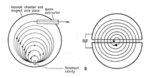
Figure 14: Sketch of a Microtron (a) where all the trajectories with increasing radii go through the same location of the accelerating RF cavity, and of a Cyclotron (b) where the trajectories spiral toward to larger radii and traverse a region where RF accelerating field is applied [55].
The first variant corresponds to microtron acceleration for electrons. The second variant represents the cyclotron acceleration for heavy particles (ions). So, we have constant magnetic field and variable radius in microtron and cyclotron and magnetic field variable in time and fixed radius in betatron and synchrotron.
Microtron Acceleration Principle
The idea of microtron acceleration (Veksler 1944 [56]) consists of accelerating electrons in a resonant cavity with the frequency of constant RF voltage, located in a constant magnetic field, so that the particles gain energy per rotation equal to the rest energy.
Synchronism is obtained when the energy gain per turn is a multiple of the rest energy: (∆E)/turn = integer.
In this way, the particles receive a single acceleration per rotation in a toroidal resonator; they perform more rotations to obtain the established energy. With each rotation, the energy increases, its radius becomes larger, and the trajectories are cotangent.
For the particle to be resonant, the time between two consecutive passes must represent an integer number of periods of the accelerating voltage.
The magnetic field B and the energy gain, w ≡ qURF/m0c2 = ∆E/E0 are adjusted so that the revolution time T1 in the first orbit equals an integer number of RF periods and increasing transit time for any two successive orbits, Tn+1 and Tn, should also be an integer number of periods:

Here, a represents the acceleration mode of the first orbit and b represents the value of the mode jump from one orbit to another, a and b are integers corresponding to a multiple of RF periods, TRF.
Starting from the relation 2π/T0 = eB/m0 we deduce:
– the energy gain per rotation required for the electron to remain resonant
![]()
where obviously a = 2,3,4,.., b = 1,2,3,… and a >b;
– the magnetic field
![]()
– the resonance condition
![]()
The mode of operation for which a = 2 and b = 1is called the fundamental mode. By choosing the right coefficients a and b, we can choose a regime of operation of the microtron to allow the pulsed power supply of the resonator, in order to increase the average value of the accelerated current, as for example, in order (b, a, w, U cos φs[kV], Pe[kW], B[T]) for φs = π/4, we can have: (1, 2, 1, 511, 520, 0.107) or (1, 8, 1/7, 73, 11, 0.0153).
The rest energy of the electron being relatively small, E0 = 0.511MeV, compared to the high energy of the proton E0 = 938.27 MeV, the acceleration is done only for electrons, the accelerator sometimes being called “electron microtron”.
The main advantages of the microtron are: 1 it uses a single cavity for acceleration, which reduces the complexity of the RF structure, and 2. the nature of the separate orbits of the microtron allows easy beam selection and extraction compared to the betatron or cyclotron.
The microtron incorporates the advantage of the betatron to have high energy in a small space, the betatron providing a small current, and the advantage of the linac to provide a large current, the linac (LINear ACelerator) having large linear dimensions [57-58].
The first microtron used in medical applications was in 1955. Today, microtrons are used as sources of medium energy electrons or as high-energy accelerator electron injectors.
Cyclotron Acceleration Principle
The cyclotron (acceleration method and associated apparatus) was patented by Lawrence in 1931 [59]. A model (80 keV and D ≈ 15 cm diameter) was made in 1932. The author received the Nobel prize (1939) for “Invention of the cyclotron and results obtained with it, especially with regard to artificial radioactive elements”
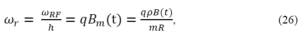
The principle of cyclotron acceleration is based on the resonance between the frequency of rotation of the particle, ie the cyclotron frequency ω0 (≡ 2π (v / 2πR) = qB / m0) and the frequency of the RF voltage, ωRF (see V (t) = V0 cos ωRF t),
![]()
Here R (t) is the variable radius that grows spirally after each revolution period of the particle T0 / 2 ≈ TRF / 2, when the potential on the dee changes its polarity,
![]()
The voltage is applied between two dee to accelerate the particles as they pass through the gap, the whole system being in a constant magnetic field.Also, the resonance occurs when ωRF = hωrev, where his the harmonic number (ratio of RF to particle frequency).
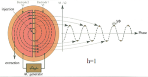
Figure 15: Syncronism in cyclotron [60].
The sketch for easier understanding of synchronism is presented in (Figure 15) [60].
From the figure it can be seen that the synchronism is performed, each time, when the radiofrequency half TRF / 2, is equal to the time of movement of the particle along the half circle which represents the semi-period of revolution of the particle in the magnetic field.
The resonance acceleration regime starts from the center of the magnet, where the ion source is placed, outward.
The kinetic energy of the ions with charge q = eQ, atomic mass A, and rest energy E0 = Am0c2, at the end of the cyclotron acceleration, in the nonrelativistic regime (T < E), is determined by the relation
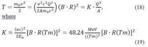
is the factor of a cyclotron corresponds to the maximum kinetic energy a proton can reach for the accelerator’s maximum magnetic rigidity, B0(Rmax) = (Bρ)max,. Here we have ion mass equal with atomic unit mass (m0 = mu = 931.5 MeV/c2)).
Currently, conventional cyclotrons have various uses in the medical field, of which we mention: PET radioisotope production Hospital 10-12 MeV, 50 μA, PET radioisotope production Hospital or industry 15-25 MeV, 100-400 μA, SPECT radioisotope production Research lab. or industry 30 MeV, 500-1000 μA and Radioisotope production or research Research laboratory 70 MeV, 500-700 μA [61].
The idea of hadron therapy appeared in 1946 in an article written by R. Wilson [62] proposing the medical use of protons produced by high energy accelerators. His idea was first realized when 30 patients were treated with protons at Lawrence Berkely Laboratory (LBL) in 1954.
In the following years, other treatments were performed in other research centers, such as: Uppsala in 1957 and Harward in 1963. Proton therapy was done with new facilities that become operational in Russia (Dubna in 1967, Moscow in 1969 and St. Petersburg in 1983) and in Switzerland at the PSI center in 1985.
Synchrocyclotron Acceleration Principle
When the energy of the particle increases due to the increase of the particle mass with the relativistic factor γ = (1- β2)-1/2, β ≡ v/c, the particle frequency differs by the frequency of the electric acceleration field, ω0 ≠ ωRF, and the resonance phenomenon disappears. The mass being at the denominator of the expression of the ion revolution period
![]()
in order to maintain the resonance of the cyclotron acceleration, the frequency of the radio frequency band ωRF (t) must decrease synchronously with increasing mass of accelerating particles γ(t), so
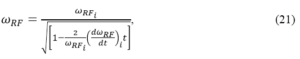
where ωRF,i and (dωRF,i/dt) are the initial values of the quantities considered.
This relationship represents the basic principle of synchrocyclotron acceleration or principle of the frequency modulated (FM) cyclotron because it operates only on frequency [63].
Thus, the synchrocyclotron has: the equilibrium orbit of accelerated ions is cyclic-spiral R0 = f (t), the magnetic field is constant B = const, the angular velocity depends on time ωrev = f (t) through the factor γ, and the acceleration frequency ωRF = f (t), decreases synchronously with increasing particle mass. The mechanism of transverse focusing of the particles is exactly like the classic wake focusing type cyclotron.
Compliance with the resonance condition by modulation of the cyclotron frequency for tracking the frequency of rotation of the particle allowed the possibility of resonant acceleration up to unlimited energies. The maximum energy of the synchrocyclotron is limited by constructive considerations. The kinetic energy of an ion (Q, A) normalized to a nucleon Tu ≡ T / A [MeV / nucleon], and the magnetic rigidity BR [Tm], can be calculated using the equation
![]()
where the atomic mass unit u of a nucleon is based on the ion 12C6+, mu ≡ m (C126+/12 = 1u = mu = 931.5 MeV/c2, and (ec)2 = (299.8 MeV/T.m)2. For proton, m0 = 938.27 MeV/c2, the nucleon mass A = m0 /mu = 1.007.
Synchrocyclotron is also characterized, apart from the natural pulsation of the beam, which is a consequence of the resonant acceleration, by an intrinsic pulse, due to the fact that the acceleration frequency is variable. For focusing in the longitudinal direction, the principle of phase stability or the principle of autophasing is applied. It was demonstrated by Veksler in 1944 [64] and McMillan in 1945 [65].
The basic idea of this principle is that, in the semi-acceleration period of the particles, we must find a reference phase, called the synchronous phase, around which all the particles that are involved in the acceleration process, execute oscillations of marginal amplitude.
It applies to all high energy resonant accelerators, both cyclical and linear. This principle was developed for each type of resonant accelerator, taking into account the trajectory shape and focus mode, (Figure 16) [3].
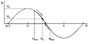
Figure 16: Principle of phase stability in the synchrocyclotron.
The area of stable motion in longitudinal phase space (the “buket”) is finite, being largest for φs =π/2 and falling to zero as φs → 0 at peak voltage. A compromise chois of φs ≈ π/3 provides both acceleration and acceptance.
The current provided by the synchrocyclotron is pulsed and the average intensity is decreased, the latter being a disadvantage for the synchrocyclotron. The values of the accelerated particle currents in the synchrocyclotron are in the 1-10 μA range. The energies of the synchrocyclotrons (or the phasotrons) built are between 100 MeV and 1000 MeV, limited not by relativity but by economics.
The synchrocyclotron also called phasotron with the highest energy is the one built in Gatchina, near Petersburg, with a diameter of the magnetic pole of 6.85 m and a weight of about 7874 tons, which provides a beam of 1μA (1012 -1013 protons / s) with energy of 1GeV.
Currently, Still River Systems Monarch 250 TM Proton Therapy System (SRS) using superconducting magnet technology (B ≈ 9 Tesla) has developed a medical synchrotron for 50-250 MeV protons (see Figure 16 [66]). It provides a single proton beam and requires a single treatment room. Its main parameters are presented in Table 3.
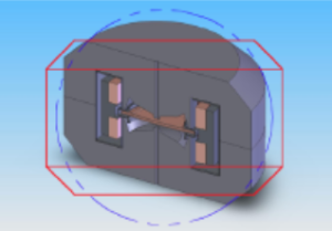
Figure 17: SC Synchrocyclotron Monarch 250 MeV, protons, 9T field, weight 20 tons with 9 T field [66].
Parameter
Value
Accelerated particle
Proton
Final energy
250 MeV
Beam intensity
40 nA (100 nA design)
Injection type
Internal PIG source
Magnetic field: central/extraction
8.9-8.2 T
RF system
One 1800 dee
Extraction type
Self-extraction
Cyclotron diameter
1800 mm
Cyclotron height
1600 mm
Cyclotron weight
25 t
Isochronous Cyclotron Acceleration Principle.
The major disadvantage of the synchrocyclotron is the reduced average beam intensity 103-104 times lower than the beam extracted from the source. The isochronous cyclotron acceleration eliminates this disadvantage by maintaining the constant frequency, providing an increasing magnetic field with the radius Brez = B0,rez (1+ b.r2) according to the same law of variation of the particle mass accelerated with the radius, m = m0 (1 + b. r2), the mass being at the denominator of the relationship ω = const = qB/ m. Here B0,rez is the induction of the magnetic field in the center of the magnet (r = 0) where the ion source (the injector) is located.
In this way the resonance is ensured by increasing the magnetic field, but the focus of the accelerated beam breaks because the magnetic field must decrease with the radius. Difficulties in accelerating the ions to high energies related to satisfying the resonance conditions and focusing the beam lasted a long period of time.
In 1938 Thomas proposed an original solution which consisted of the renunciation of the magnetic field with axial symmetry and proposed the use of a magnetic field with azimuthal variation. Discovering the principle of phase stability that allows the acceleration of charged particles to high energies, delayed the implementation of the field with azimuthal variation. In 1950 the principle of intense focus appears.
The problem of azimuthal variation is solved after the emergence of the FFAG concept (1950) in 1955 when Kerst and co-workers propose the use of an azimuthal and radial magnetic field or in short, a magnetic field with spatial variation. A sketch is shown in (Figure 18) [68].
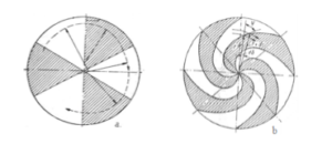
Figure 18: Principle of isochronous cyclotron acceleration: a-radial sector and b-spiral sector.
The principle of isochronous cyclotron acceleration consists in maintaining the resonance at a fixed rotational frequency at acceleration by increasing the magnetic field of guide Bres (r) with the radius to ensure the isochronous radial stability with the increase of the Lorentz factor γ, and the azimuthal variation of the magnetic field to ensure the transverse stability using the principle of alternating gradient focusing (1952).
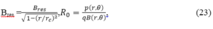
where, Bres(0) = ce/ωRF.E0, rc =c/ωRF, and E0=m0c2.
This principle, schematically, can be presented in two variants: with radial magnetic sectors or with spiral magnetic sectors.
In the case of the magnetic structure with radial sectors (Figure 18a), the radial growth of the magnetic field ensures the radial stability in better conditions than in the classical cyclotron. In order to ensure axial stability, the law of azimuthal variation of the magnetic field is of the form: Bz(0) = Bzm(1- f·sin pθ), where f is a subunit modulation factor, Bzm the average value of the field on the radius circle rm and p a positive integer factor. In this case, the frequency of axial betatron oscillations is νz2 = f2/2 +1 – γ2, and of the radial ones νr2 = f2/2 + 1. The modulation factor cannot be made greater than 0.25, so for γ> 1.03 the axial stability disappear.
Higher axial force is possible by bending the edge of the magnetic piece (the edge effect) from one area to another, within the magnetic structure with spiral sectors (Figure 18b). In this case [6] we have the frequencies of radial betatron oscillations νr2 = γ2 and axial νz2 = f2 (1/2 + tg2 ψ) +1 – γ2. The isochronous cyclotron is limited by the resonance νr = 2, which is difficult to pass. The resonances are dangerous for γ = 1 and γ = 2.
Seen from the outside C 400 Isochronous Cyclotron shows as in (Figure 19) [69]. The main parameters are presented in (Table 4) [67].
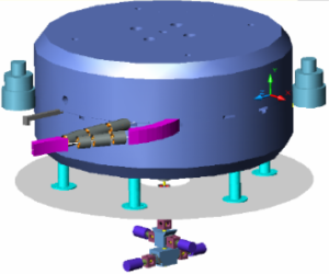
Figure 19: C 400 Isochronous Cyclotron [69].
Parameter
Value
Cyclotron type
Compact, isochronous
Accelerated particle
H2+, 4He2+, 12C6+
Final energy: ions/protons
400 MeV/u/265MeV/u
Carbon beam intensity
8 enA
Injection type
ECR, ECR, multi-cusp
Central magnetic field
2.5 T
Sector shim type, spiral angle
Archimedean spiral,730
RF system
Two spiral cavities
Operation RF harmonic
4
RF frequency
75 MHz
Peak dee voltage: center/extraction
80 kV/160kV
Final radius
1850 mm
Extraction type: ions/protons
Deflector/Stripping foil
Cyclotron diameter
6600 mm
Cyclotron height
3400 mm
Cyclotron weight
700 t
The kinetic energy normalized to the atomic unit of mass Tu for a particle (Q, A) is given by the known relation
![]()
Where Eu = 931.5 MeV and Bm and Rm are mean values for the magnetic field and the radius of extraction from the accelerator.
In this type of cyclotron, the magnetic field is dependent on r and θ. The polar parts of the electromagnet are profiled so as to ensure correct dependencies of r for the average magnetic field Bm(r) required for synchronism. The polar pieces along the circular orbit have “valleys” and “hills”. The connection between these profiles is made with the straight and spiral regions.
The isochronous cyclotron ensures high intensity of the accelerated beam and has the possibility to operate continuously at low acceleration voltages. It can provide proton and ion beams at energy required for radiotherapy. The final energy is adjustable to large limits by the variation of the induction value in the center.
Synchrotron Acceleration Principle
Synchrotron acceleration is based on the use of longitudinal RF electric fields, created locally in RF cavities in which the energy transfer from the RF electric field to the particle occurs, and a time-varying magnetic field, which ensures the accelerated particle movement along the circular trajectory, according to relationship
![]()
Here, R is the radius of the trajectory, q – particle charge, B(t) – magnetic field and E(t) = (q2c2R2B(t)2 + m02c4)1/2is the total particle energy. The magnetic field B (t) can be linearly in slow cycling synchrotron (≤ 1Hz) or sinusoidal in fast cycling synchrotron (≥ 3Hz).
The principle is valid for both electron synchrotron acceleration and protron synchrotron acceleration.
Typically, the RF frequency is not identical to the revolution frequency. Using the relation RBm = ρB, the ratio between them is called the harmonic number h,
and it is an integer. In that case, the circumference of the accelerator will be divided into h sections. Within each section a stable region will be created and populated by particles. We called the frequency of rotation of the particle, the reference, which meets the wave at the same phase, the synchronous frequency ωs and the corresponding phase – the synchronous phase Φs. The rotation period is given by relation Trev= 2πh / ωRF
Using the ratio of total energy in the expression (24) results immediately the expression for the RF frequency
![]()
where we have noted the radius of the local orbit with ρ. It is seen that the RF frequency increases during the injection-extraction period to maintain resonance.
The energy gained by the synchronous particle is
![]()
It results for the synchronous particle phase, sin Φs = (∆E) rev / qVRF, two solutions: Φs and π – Φs, the first – stable, the second – at the limit of stability
In the synchrotron accelerator the particles are accelerated on a circular trajectory, which significantly reduces the weight of the iron and allows obtaining much greater energies than in the synchrotron. Magnetic fields up to 1.6 T can be generated by conventional magnets and 5 – 9 T superconducting magnets.
In some versions, the guide field acts only in the area of the circular path of equilibrium. In most synchrotrons (electron synchrotrons and proton synchrotrons or synchrophasotrons) the trajectory contains rectilinear sections used for placing injection, acceleration and extraction systems. In this case, the trajectories are formed by circle arcs separated by straight lines along which the magnetic field does not exist.
Transverse stability is ensured either by weak magnetic focusing (0 < n < 1), or by intense focusing or alternating gradient (| n | >> 1).
In the case of the synchrotron with rectilinear sections, the axial focusing can be achieved by the effect of the escape field at the crossings from the field sectors to those without field and vice versa, the gradient inside the field sectors can be null. This focus mode is called zero gradient focusing (ZGA).
(Figure 20) presents the principle of phase stability in the synchrotron, discovered by Veksler and MacMillan.
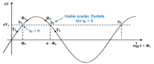
Figure 20: Principle of phase stability in the synchrotron.
In summary, if an increase in energy is transferred into an increase in velocity, R1& T1 will move toward S1 (stable), while R2& T2 will move away from S2 (unstable).
Starting from the period of revolution of the particle Tr= C / βc and of the compaction moment factor αc defined by dC / C = αc .dp / p or dR / R = αc. dp / p) results the moment of compaction ηc
where ωr = ωs is the revolution frequency around the synchroton, αc = 1/γtr2 – the momentum compaction factor, a function of transverse focus, and factor γtr is the transition energy of synchrotron.
Stable phase focusing can be obtained in either case, if the RF synchronous phase is chosen as follows:
When accelerating hadrons through γtr, the RF phase must be switched abruptly from Φs for ηc > 0 to π – Φs for ηc< 0 (Figure 20).
The nonsynchronous particles execute oscillations around the synchronous particle due to the energy gain, different from that of the synchronous particle (Figure 20).
These oscillations cause radial deviations (R = R0 + ∆R) which have, like their corresponding phase deviations (Φ = Φs + ∆Φ), an oscillatory character. Radial oscillations, different from the betatron ones, were called synchrotron oscillations whose frequency was noted with Ωs.
Small-amplitude synchrotron oscillation equation is
This is the principle of phase focusing and is a fundamental process to obtain stable particle beams in circular high energy accelerators.
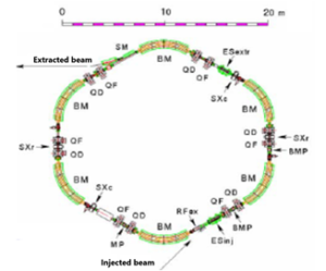
Figure 21: Heidelberg Ion Therapy Synchrotron [71].
Parameter
Step
Protons
Carbons
Energy
255
48 – 221 MeV/u
88 – 430 MeV/u
Penetration
255
20 – 300 mm
20 300 mm
Beam Size
4
8 – 20 mm
14 – 12 mm
Intensity
10
8.107 – 2.108
2.106 – 8.107
Ions/Spill
10
4.108 – 1.1010
1.107 – 4.108
Place
3
H1, H2, QA
H1, H2, QA
It results from Table 5 that the beam is delivered in three separate treatment rooms. Facilities based on accelerators which deliver beam to multiple rooms (multiple-room accelerators) are typically more economical than those based on single-room accelerators.
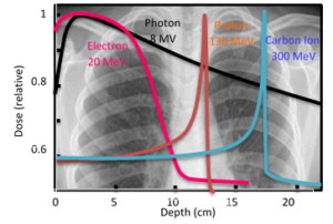
Figure 22: The distribution of the absorbed dose in depth for electrons, photons, protons and carbon ions in water phantom.
These dose distributions were superimposed over a section of the irradiated area to see how the energy of the particles, the absorbed dose, the irradiation fields and the iosodoses were chosen in order to establish some elements of the radiation treatment plan [74].
As in the case of particle beam therapy (electrons and photons), the beam of heavy particles (protons and ions) at the exit of the accelerator, being considered punctual, is widened by means of a scattering device, another of dose homogenization in the transverse plane and adaptation of the isodoses to the target volume (irradiation) according to the standard irradiation fields established (Figure 23) [71].
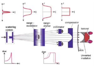
Figure 23: The various stage in passive beam delivery [71].
The upper part shows the dose distribution in the transverse plane (2D) and below, on the axis of the beam in depth.
FFAG acceleration principle
The idea of accelerating in fixed field and alternating gradient (FFAG) came after patenting the principle of focusing with alternating gradient (Christofilios, 1950 [72]) and publishing the paper“ The Strong-Focusing Synchroton—A New High Energy Accelerator” by Courant, Livingstone and Snyder in 1952 [73].
Starting from this idea, MURA built the first configuration of FFAG radial accelerator sector of 400 keV in 1956 (Inventor: Keith Simon, Andre Kolominski, Andre Lebedev, Tihiro Ohkaiwa) and the first configuration FFAG spiral sector accelerator 125 keV in 1957 (Inventor: Donald Kerst) [74].
The FFAG acceleration principle is based on the use of cavities to transfer energy to the particles that cross it several times during their circular motion, in an area with a constant magnetic field that guides charged particles along a closed orbit.
The particle describes a circular trajectory, whose radius R indicates the equality between the centrifugal force and the centripetal force,
![]()
where p is the moment, q is the charge of the particle and B is the magnetic field. The maximum radius is determined by the maximum magnetic field provided by magnets.
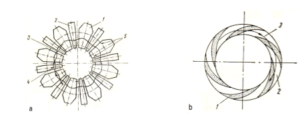
Figure 24: Principles of FFAG acceleration: a. FFAG with radial sectors: 1. Centrifugal sector with normal field, 2. Centrifugal sector with inverted field, 3. Particle trajectory; 4. Orbit of equilibrium, 5. Radial limits of acceleration chamber; b. FFAG with spiral sectors: 1. Magnetic field with intense field, 2. Sector with field weak, 3. Particle trajectory [68].
The structure of the magnetic field in the vision of FFAG accelerator with radial sectors and FFAG accelerator with spiral sectors is shown in Fig. 24. In this figure we observe the narrowing of the field of orbits to be covered with the magnetic field of guidance, just as in the synchrotron, in both versions, compared to the synchrotron and the isochronous cyclotron, which have magnetic field from the center to the final radius (Figure 20). The beam focusing schemes are determined by the magnetic field configuration: one is the radial sector focus and the other the spiral sector focus. Radial sector focusing uses a combination of positive and negative bending magnets to create strong beam focusing with FODO lattice configuration. In spiral sector focusing, edge focusing is used efficiently [75].
In order to narrow the ray range to be covered by the magnetic field of guidance, the radial variation of the magnetic field is more pronounced than the synchronous law. The magnetic field is in shape
![]()
where B0 is the central magnetic field of reference, r is radially coordinated with the origin at the center of the accelerator, R0 is the distance between the center of the accelerator and the center of the magnet and k is the index of the magnetic field. There are two types of magnets: linear when k = 1 and non-linear when k ≠ 1.
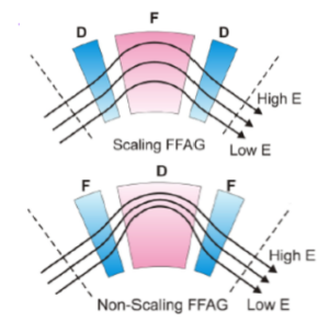
Figure 25: Principles of a Scaling SL FFAG and b. non-scaling NL FFAG. Orbits patterns. Positive-bending fields are shown in pink, negative in blue, with the colors density indicating the field strength [76].
To avoid slow resonance, the shape of the orbit, the beam optics and the components are maintained during the acceleration process by keeping the index k constant. The FFAG operating on this principle is called the FFAG scaling (S-FFAG) (Figure 25a).
In the case of fast acceleration, there is no time to deteriorate the quality of the beam as it crosses the resonances and as a result it is not necessary to maintain the orbit shape, beam optics and frequencies (tunes). Those FFAGs where k is not constant are called non-scalable FFAGs (NS-FFAGs) (Figure 25b) [77].
An advantage of non-FFAG scaling is that it can be built using magnets that are less complicated than the magnets required for FFAG scaling.
In 2011 there were a number of FFAG-based complexes in design (D), testing (T) or operation (O), of which we mention [53]: KURRI radial sector S-FFAG, (O), k = 7.5, p, 20-150 MeV, 60 Hz, 5.12 m; Kyushu radial sector S-FFAG k = 7.5, – 125 MeV, 100 Hz, 5.5 m, Inj.: 10 MeV cyclotron; RACCAM spiral sector S-FFAG, (T) 70-180 MeV, 3.46 m, Inj.: 15 MeV cyclotron; Chiba S-FFAG, (D), k =10.5, 100-400 MeV, 200Hz, 10.8 m; MEICo-p, spiral sector S-FFAG, (D), k = 10.5, -230 MeV, 2000 Hz, MEICo – C, spiral sector S-FFAG, (D), k = 12, 7-400 MeV, 500 Hz, 7 m.
Also, there were several in design Non-scaling FFAG-based complexes, of which we mention: Lin. NS-FFAG w p/C, 31-250 MeV/8-69 MeV, 6.87 m; Lin. NS-FFAG cC, 69-400 MeV, 8.25 m; Lin. NS-FFAG, p, 31-250 MeV, 4.28 m; PAC Non Lin NS-FFAG, c, p, -250 MeV, 3.4 m, PAC Non Lin NS—FFAG, C, 60-400 MeV, 6.9 m and PAMELA project (Partcle Accelerator for MEdicaL Aplications) Non Lin. NS FFAG (D) p, 31-250 MeV, 1000 Hz, 6.25 m, Inj.: cyclotron; FDF triplet cells.
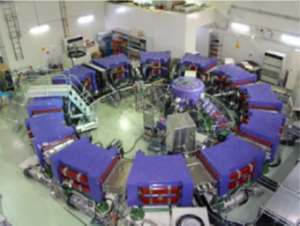
Figure 26: The 150 MeV proton radial sector FFAG accelerator from Kyushu University [78].
Being S-FFAG it has the field index k = 7.5 and accelerates protons from 10 to 125 MeV at the frequency of 100 Hz. It has a diameter of 11m and the total length of the average orbit of about 35m.
He moved from KEK to Kyushu University in 2008. The injection source is a 10 MeV cyclotron located in the center of the ring.
Among the non-scaling FFAGS we chose the PAMELA project [79]. PAMELA is a nonlinear NS-FFAG that will accelerate protons from 30 to 250 MeV (field factor k = 38), and carbon ions frem 68 to 400 MeV/u. The repetition rate of the machine is 1 kHz. A schematic layout of PAMELA is shown in (Figure 27).
The main objective of this project was to design a particle therapy facility using an NS-FFAG.
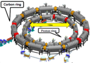
Figure 27: Proposed PAMELA layout [80].
The main parameters of the PAMELA projectwith two concentric FFAGs are presented in (Table 6).
| Parameter | Ring 1 (proton, carbon) | Ring 2 (carbon) |
| Energy | 30 – 250 MeV (p) | 68 – 400MeV (C) |
| 8 – 68 MeV/u(C) | ||
| Diameter | 12.5 | 18.4 |
| k value | 38 | 41 |
| Orbit excursion | 18 cm | 21 cm |
| Revolution | 1.94 – 4.62 MHz (p) | 1.94 – 3.91 MHz (C) |
| frequency | 0.98 – 1.92 | |
| Maximum field | 3.6 T | 3.5 T |
| Magnet | FDF Triplet | FDF Triplet |
| Superconducting | Superconducting | |
| Length | 57 cm/magnet | 113 cm/magnet |
| Aperture | 25 cm | 33 cm |
| Long drift | 1.3 m | 1.2 m |
| Voxel size | 4x4x4 ≈ 10x10x10 mm | |
| Dose field size | 100×100 ≈ 250×250 mm | |
| Dose rate | 2 ≈ 10 Gy/min | |
| Repetion rate | 0.5 ≈ 1 kHz | |
/Table 6: Main parameters of PAMELA.
As a complement to FFAGs for therapy we mention NS-FFAG gantry presented by D. Trbojevic, E. Keil, and A. Sessler, in work Non-scaling FFAG Accelerators and Gantries for Medical Purposes, ICFA, Beam Dynamics Newsletter, No. 43, august 2007, 115-125, Editors; C.R. Prior and W. Chou [81].
The proton irradiation head is made of Non Scaling FFAG cells, with a magnetic field small enough that permanent magnets can be used.
Superconducting magnets made without iron could be used to reduce the size (probably by a factor of two). The reduction in weight of the irradiation head should be two orders of magnitude.
The proposed irradiation head (Fig. 28) has a weight of about 1.5 tons compared to the conventional isocentric irradiation weight of ~ 130 tons.
Figure 28: Proton gantry made of NS FFAG cells [81].
In particular, for carbon ions, the existing gantry at the Heidelberg Ion Therapy Center is both large and heavy, weighing in at 630 t, where 135 t of that are the magnets and the remainder is the supporting structure to allow rotation around the patient.
New Version of Acceleration
Principle of Dielectric Wall Acceleration
Dielectric Wall Accelerator (DWA) is a new concept for a high gradient acceleration. The principle of operation is that of conventional induction accelerators with the mention that it uses dielectric material instead of the central magnetic pole of acceleration. The use of dielectric material in the DWA accelerator allows an acceleration gradient of the order of 100 MV / m. With this high gradient it is appreciated the development of compact accelerators for proton therapy. DWA was patented in 1990 and approved in 1998 [82].
Principle of Dielectric Laser Acceleration
The principle of dielectric laser acceleration (DLA) is based on the electron acceleration using evanescent electromagnetic waves in the vicinity of a dielectric structure. The near-field electron acceleration scheme represents the inverse Smith-Purcell effect [83-86].
Demonstration of the Smith – Purcell inverse effect in the optical regime represents a new method of acceleration with acceleration gradients of the order of 1GeV / m. These gradients surpass those of the RF acceleration structures and approach those of the acceleration through a plasma wave that is excited by an intense laser pulse in relativistic regime.
Laser Acceleration Principle
Leaving aside the electrostatic accelerators based on the technology of high voltages, all linear and circular accelerators mentioned in this paper are based on the conventional technology of longitudinal radiofrequency electric fields. This means that the Newton-Lorentz formula used only the first term referring to the longitudinal electric field (<50 MV / m) for acceleration.
Advanced in laser technology allowed the creation of an Apollo Laser System, on Magurele Platform near Bucharest, a system that can generate laser beams (10 PW, 15 fs, 150 J, 1023 W / cm2) that can be used for technological research on the parameters of clinical laser accelerator [17].
Figure of merit of the laser system is the dimensionless intensity parameter of the peak amplitude of the transverse electric field of a linearly polarized laser pulse in vacuum EL (= 2.7 x 10⁻⁹ I01/2(W / cm2)), a0 ≡ eEL / mcω, related to the peak intensity of laser I0 through
![]()
In relation (35), I0 [W/cm2] = EL/τ.Aeff = Pp/Aeff, EL = Pp·τ is the pulse energy, Pp is the peak power, Aeff = πr02/2 = 20.λ2 [μm2], is the laser beam cross-section, τ is the pulse time, w0 is the radius of the laser beam at focus, Ep = (2 Z0Pp/Aeff)1/2 is the peak electric field, Z0 = 377 Ω is the free space impedance and ξ = 1/2 for linearly/circularly polarized laser.
In the case of laser acceleration, when a relativistic laser pulse irradiates a thin target, with the thickness and density of ne electrons, the electrons are rapidly accelerated up to ve ≈ c by the transverse electric field E⊥. The longitudinal electric field Eǁ determined by the second term of the Newton-Lorentz force pushes the electrons forward (longitudinally) with the force eEǁ ≈ ev⊥ x B⊥ / c, where B⊥ is the magnetic field of the laser pulse. Laser acceleration is based on the second term of the Newton-Lorentz formula.
The relativistic regime for electrons reaches at radiation intensity of I0 ≥ 1018 W/cm2 (or a0 > 1), and for protons and carbon ions at I0 ≥ 5×1024 W/cm2 (or a0>1836). In this regime the laser system can provide X – ray and XUV beams.
Laser-Driven Clinical Electron Beams.
The electron acceleration controlled by the laser can be done in vacuum, gases and plasmas [14]. Because the phase velocity of the optical fields (ω, k) is faster than the speed of light (vp = c (1+1/kZR) > c), they cannot be used to accelerate electrons. Here ZR = k r02/2 is the Rayleigh length and r0 is the minimum spot size. Acceleration can occur only by limiting the interaction distance.
To reduce the phase velocity of the laser wave, disturbing elements are introduced into the interaction region. Of these we mention: a gas and we deal with the principle of inverse Cerenkov acceleration, a periodic magnetic field and we get the principle of inverse free electron laser acceleration, or a dielectric network and we have the principle of inverse Smith-Purcell acceleration.
There is also the vacuum beat wave acceleration (WBWA) principle, which consists of two laser beams of different wavelengths, λ1 and λ2, which co-overlap in the presence of an injected electron beam.
For plasma electron acceleration there is also the principle of the plasma beat wave acceleration (PBWA) and the principle of the laser Wakefield acceleration (LWFA) [44].
Laser-Driven Clinical Hadron Beams.
In the case of hadron radiation therapy, IAEA TRS-398 recommends energies of 50-250 MeV for protons and energies of 100- 450 MeV / u for carbon ions.
The values of such kinetic energies are required to provide the penetration of the hadrons beams at the level of the malignant tumors located in depth ranging between 3 cm and 38 cm.
At present there are several mechanisms to accelerate hadrons by means of laser radiation, each of them with its advantages and disadvantages. Among these known mechanisms the following are worth mentioning Target Normal Sheats Acceleration – TNSA, Break – Out Afterburner – BOA, Coulomb Explosion Radiation Acceleration – CERA and the acceleration mechanism by radiation pressure – RPA [87-90].
The acceleration mechanism which often dominates the interaction between a laser and foil is known as target normal sheath acceleration (TNSA).The TNSA principle consists in laser irradiation of a solid target of a few μm. The laser energy is absorbed by resonant heating mechanisms, a population of hot electrons is created throughout the target width, reached the target surface, they escape in vacuum forming a cloud loaded by hot electrons, a electrostatic field is generated which accelerates ions from the rear of the target. Experimental research conducted so far with Laser intensity > 1019 W/cm2, pulse length: 10 -100 fs, and a few μm Titan target indicate the following achievements: Maximum energy: protons ≈ 67 MeV, carbon ions ≈ 40 MeV/u; high brightness: >1012 protons in ps pulse; source size : ≈ 100 μm (virtual source ≈ 10 μm); emmitance εN ≈ 0.005π mm.mrad; energy conversion efficiency up to 10%, (Figure 29) [91].
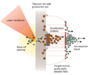
Figure 29: Principle of TNSA [91].
As for the RPA principle, it has two versions. The first one is the “Laser Piston acceleration” – LPA or the “Light Sail acceleration” – LS-RPA, a regime initiated and developed by Esirkepov & co. and Macchi & co. [92-94], This principle implies the acceleration of ions by an electric field between separate charges – electrons and ions – Eǁ = 2πeneℓ < EL, which does not depend on the distance between ions and electrons.
Regarding the first version, the research results are presented in (Figure 30) [93].
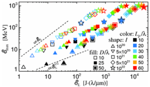
Figure 30: Proton maximum energy vs. laser pulse energy. The dashed lines exemplify possible scaling [93].
This shows the maximum energy of the proton ℰmax [MeV] versus the laser pulse energy ℇL in the case when the target thickness ℓ = λ and ne =100 ncr, for intensities I0 = 1020-1022 W/cm2; ratio between the laser pulse length Lp and laser wavelength Lp/λ; and ratio between the focal spot size D and the laser wavelength D/λ.
The interpretation of the data in (Figure 27) obtained in the RPA LS acceleration regime indicates that the proton energy is proportional to the square root of the laser energy ℰmax ≈ ℇL½.
The second version called the “Hole Boring” – HB mode of RPA, was initiated and developed by S. Wilks, A.P.L. Robinson & co. and S.M. Weng and co. and experimental by S. Kar & co. [95]. This assumes that the layers of electrons and ions are considered to be a plasma mirror that propagates with the laser beam.
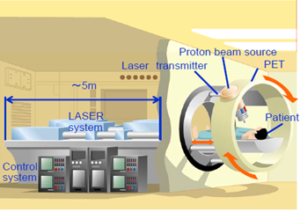
Figure 31: Conceptual laser accelerated proton therapy instrument [96].
In (Figure 31) authors [96] propose the concept of radiotherapy combined with the PET camera. In this way, the radiation oncologist is allowed to provide the patient with a more accessible and precise cancer therapy.
Conclusions
- The conventional RF technology for therapy particle accelerations based on RF longitudinal electric field component of TM or TE – degenerate modes, that causes the energy exchange between wave and beam.
- At first radiation therapy (photons and electrons) was performed with betatrons and linear accelerators, the latter taking the place of the first, removing their disadvantages related to the high weight and low intensity of the accelerated particle beam.
- Hadron therapy (protons and carbon ions) was and is performed with cyclotrons and synchrotrons, the first having the disadvantage of heavy weights and the others having the disadvantage of large rays (trajectories). The fast cycling synchrotron gains ground because that eliminates the magnetic field in the central area and leaves the magnetic field only in the area of circular orbit to guide the particles in the acceleration process.
- In addition to cyclotrons and synchrotrons, FFAG therapy accelerators are developed which provide high beam intensities, have a smaller radius, and the magnetic field covers only the area of the orbits.
- Laser technology in domain powers > 1 PW (=10 15 W) will allow the use of the component of the longitudinal electric field of the TEM wave to accelerate the therapy particles to energies in the therapy domain.
- In laser class, we have TNSA acceleration that generates energies between 70-100 MeV and acceleration of RPA that has no energy limit for particles that accelerate.
References
- Bevalacqua JJ (2007) Health Physics in the 21st Century, WILEY-VCH Verlag GmbH & Co. KGaA, 2007.
- Bryant PJ. A Brief History and Review of Accelerators, CERN, Geneva, Switzerland
- Craddock MK, Symon KR (2008) Cyclotrons and Fixed-Field Alternating-Gradient Accelerators, TRI-PP-08-24.
- Griffiths D (2008) Introduction to Elementary Particles, ISBN 978-3-527-40601-2.
- Humphries S (1985) Principles of Charged Particle Acceleration, QC787.P3H86 1986 ISBN 0-471-87878-2.
- Kolomensky AA, Lebedev AN (1966) Theory of cyclic Accelerators, (North Holland Publihers Comp. Amst. 1966).
- Landau LD, Lifchitz EM (1966) Theorie du champ, Editions MIR, Moscou.
- Lawson JD (1976) Particle beams and plasmas, Edited by Hofmann A., and Messerschmid E., CERN 76-09.
- Macken JA (2015) The Univers is Only Space -Time, Santa Rosa California, Revision 8.0.
- Nagashima Y (2013) Elementary Particle Physics, Vol. 1, WILEY-VCH Verlag GmbH & Co. KGaA.
- Palmer RB (1994) Acceleration theorems, U.S. Department of Energy under Contract No. DE-ACO2-76-CH00016.
- Wiedemann H (2007) Particle Accelerator Physics, Springer – Verlag Berlin Heidelberg.
- Bulanov SV, Khoroshkov VS (2002) Feasibility of Using Laser Ion Accelerators in Proton Therapy, Plasma Physics Reports 5: 453-456.
- Sprangle P, Esarey E, Krall J (1996) Laser driven electron acceleration in vacuum, gases and plasmas, Phys. Plasmas 3: 2183-2190.
- Lawson JD (1988) Lasers, microwave tubes, and accelerators: a unified point of view, SPIE 1033: 85-99.
- Palmer RB (1981) Laser driven electron acceleration, 1981, PAC, March 11-13, 1981 Washington, D. C., 3370-3374.
- Zamfir NV (2014) Extreme Light Infrastructure – Nuclear Physics ELI-NP, ELI-NP, Bucharest, Romania.
- Hinterberger J. Electrostatic accelerators.
- Cockroft JJ, Walton ETS (1932) Proc. Of the Royal Soc. of London, A136, (1932), A129: 477.
- Van de Graaff RJ (1931) A 1,500,000 Volt Electrostatic Generator, Phys. Rev 38: 1919.
- Alvarez LW (1951) Energy doubling in d.c. accelerators, Rev. Sci. Instr. 22: 705-706.
- Slepian S (1927) X Rays – Tube, US Patent, Filed April 1, 1922 No 1,645,304.
- Wideroe R (1964) Einige historische Notizen, Wissen-Schaftliche Zeitsschrift der FSU, Jena, Jahrgang 13: 431-436.
- Wideroe R (1928) Uber ein neues Prinzip zur Herstellung hoher Spannungen, Archiv fur Electrotechnik 21: 387.
- Steenbek M (1937) Device for Producing Electron Rays of High Energy, US Patent 2,103,303.
- Kerst DW (1940) Acceleration of electrons by magnetic induction, Phys. Rev 58: 841.
- Loevinger R, et al. (1970) Annals New York Academy of Sciences, 161: 158-167.
- Scarlat F (1971) “Adaptation of the 30 MeV IAP Betatron for Medical Therapy”, Proc. of the 5th Int. Betatron Symposium, Bucharest, Romania: 479 – 487.
- Birzu I, Grigorescu St, Scarlat F (1973) Therapeutic and Dosimetric Aspects in the Treatment of Malignant the 30 MeV Betatron, Proc. of the Int. Conf. on Photonuclear Reactions and Appl., Asilomar, Livermore, USA 30: 61.
- Scarlat F, Oproiu C (1994) The 40 MeV Medical Betatron. Experience versus Predictions”, Proceedings of the EPAC-94, London, England 3: 2686.
- Scarlat F (1992) A 40 MeV Medical Betatron, Rev. Roum. Phys., Tome 6: 615-619.
- Scarlat F, et al. (1983) Romanian Patent, No. 76683.
- Haltrich S, et al. (1970) Kernenergie, Band 13, H.1, S.16-24.
- Iliescu CC (1964) Research and Development Work with the Bucharest Betatron, Wissen-Schaftliche Zeitschrift der FSU Jena, Jahrgang 13: 445-446.
- Ciorascu Fl, et al. (1962) St. Cerc. Fiz. 15, 11: 105.
- Duke PJ (2000) Synchrotron Radiation. Production and Properties, Oxford University Press, Inc., New York.
- Scarlat F, Baboi N (1997) On Synchrotron Radiation Spectrum in the Classical and Quantum Mechanical Limits, Acta Physica Polonica A 91: 757-761.
- Codling K (1973) Applications of synchrotron radiation, Rep. Prog. Phys 36: 541-624.
- Alvarez LW (1946) The Design of a Protron Linear Accelerator 41: 799.
- Slater JC (1948) The Design of Linear Accelerators, Rev. Mod. of Phys 20: 473-518.
- Ginzton EL, Hansen WW, Kenedy WR (1948) A Linear Electron Accel. Rev. Sci. Inst 19: 89-108.
- Irie K, Minowa Y, Sawada S (1973) Jap. Journal of Applied Physics 12: 277-285.
- Kapcinsky IM, Teplyakov VA (1970) Linear ion accelerator with spatially homogeneous strong focusing, Prib. Tech. Eksp., No. 2 (1970) (in Russian).
- Scarlat F (1994) Electron Accelerators. Present and Future Applications, Invited Speaker, Thirteenth International Conference on Applications of Accelerators in Research and Industry, Denton, Texas, USA, November 7- 10, EF-6.
- Scarlat F (1996) Some Consideration on the Selection of an Accelerator Transmutation of Wastes, Proc. of the Second Intern. Conf. on Acceler.-Driven Transmut. Technol. and Applications”, Kalmar, Sweden 360-366.
- Marghitu S, Marghitu O, Oproiu C, Marinc G, Scarlat Fl (2004) Nuclear Instruments and Methods in Physics Research B 217: 498-504.
- Badita E, Vancea C, Calina I, Stroe D, Dumitrache D, et al. (2017) Long term stability of the performance of a clinical linear accelerator and z-score assessement for absorbed dose to water quantity, Rom. Rep. Physics 69: 606.
- Scarlat F (2003) Proposal for a Free Electron Laser Driven by the 7 MeV NILPRP Linac, Rom. Journ. Phys 48: 369.
- Baltateanu N, et al. (1969) L’accelerateur lineaire d’electrons de 3 MeV, Contributions al’etudeet la realisation des accelerateur lineaires d’electrons, Institute of Atomic Physics, Bucharest, Romania, AL-1/1969.
- Karzmark CJ, Pering NC (1973) Phys. Med. Biol 18: 321-354.
- Thwaites DI, Tuohy JB (2006) Phys. Med. Biol. 51: R343–R362.
- Kazmark CJ, Morton R, Primer A (1981) U. S. Department of Health and Human Services, Bureau of Radiological Health.
- Verdu Andres S, Amaldi U, Faus-Golfe A (2011) Int. Journal of Modern Physics A 26: 1659-1689.
- Amaldi U, Verdu Andres S, Faus-Golfe A (2013) J. Radiat. Res. 54: 155-161.
- Ruggiero AG (2005) Brief History of FFAG Accelerators, FFAG Workshop (FFAG’05), Osaka, Japan 4-9.
- Veksler VI (1944) DAN (U. S. S. R.) 18: 46.
- Kapitza SP, Bukov VP, Melekhin VL (1962) Sov. Phys., JETP, 14: 266.
- Axinescu S, et al. (1982) “The 17- orbit microtron of the Institute of Atomic Physics”, All Union Symposium on microtrons and their applications”, Dubna, U. S. S.R.
- Lawrence EO (1932) Method and Apparatus for Acceleration for Ions, Fied Jan 20, 1932, US Patent Office, Serial No. 589033.
- Chernyaev AP, Varzar SM (2014) Physics of Atomic Nuclei 77: 1203–1215.
- Braccini S (2016) Compact Medical Cyclotrons and their Use for Radioisotope Production and Multi-Disciplinary Research, Proc. of Cyclotrons 2016, Zurich, Switzerland, 229-234.
- Wilson RR (1946) Radiological Use of Fast Protons. Radiology 47: 487-491.
- Papash AI, et al. (2010) Joint Institute for Nuclear Research, Dubna, Russia, Proceedings of RuPAC-2010, Protvino, Russia THPSC037, 393-395.
- Veksler VI (1944) D.A.N. SSSR, 43, 329, 1944 & 44, 365.
- MacMillan EM (1945) The Synchrotron-A Proposed High Energy Particle AcceleratorPhys. Rev. 68: 143.
- Antaya TA, et al. (2010) Compact Single-stage. Superconducting Cyclotron-based Primary Accelerators, DAEdALUS Workshop–MIT LNS– 4.
- Smirnov V, Vorozhtsov S (2016) Modern Compact Accelerators of Cyclotron Type for Medical Applications, Physics of Particles and Nuclei 47: 863-883.
- Teodorescu IE (1967) Acceleratoare de particule incarcate (Charged particle accelerators in Romanian), Edit. Acad. RSR.
- Karamysheva G, Jongen Y, Abs M, Beeckman W, Blondin A, et al. (2007) IBA C400 Cyclotron; Project for hadron therapy, Ion Beam Applications, JINR, Russia.
- Ondreka D, Weinrich U (2008) The HIDELBERG Ion Therapy (HIT) Accelerator Coming into Operation, TUOCG01, Proceedings of EPAC08, Genoa, Italy.
- Schardt D, Elsasser T, Schulz-Ertner D (2010) Heavy ion tumor therapy: physical and radiobiological benefits, Rev. Mod. Phys 82: 383-425.
- Christofilos Nicholas (1956) Focusing System for Ions and Electrons, Athen, Grece, Application March 10, 1950, Serial No. 148920, US Patented 2,736,799.
- Courant ED, Livingston MS, Snyder HS (1952) The Strong-Focusing Synchroton. A New High Energy Accelerator, Phys. Rev 88: 1190.
- Bertozzi W, Franklin W, Korbly S, Ledoux RJ, et al. (2011) Accelerators For Homeland Security. International Journal of Modern Physics A 26: 1713-1735.
- Sheehy SL (2015) Fixed-Field Alternating-Gradient Accelerators, Proc. of the CAS-CERN Accelerator School: Accelerators for Medical Applications, Vösendorf, Austria 26: 321-325.
- Craddock MK (2011) FFAG Optics, International Worshop on the FFAG Accelerators (FFAG’11) Daresbury Laboratory.
- Machida S. Fixed field alternating gradient, ASTeC, STFC Rutherford Appleton Laboratory, Didcot, United Kingdom.
- Kyushu University. http://www.cabas.kyushu -u.ac.jp /home /ja/ ffag.
- Yokoi T (2011) Status of PAMELA: An UK Particle Therapy Facility Project Using NS-FFAG, Int. J. of Mod. Phys. A 26: 1887-1902.
- Peach KJ, Aslaninejad M, Barlow R, Beard CD, Bliss N, et al. (2013) Conceptual design of a nonscaling fixed field alternating gradient accelerator for protons and carbon ions for charged particle therapy, Physical Review Special Topics-Accelerators and Beams 16: 030101-34.
- Trbojevic D, Keil E, Sessler A (2007) Non-scaling FFAG Accelerators and Gantries for Medical Purposes,ICFA, Beam Dynamics, Newsletter 43: 115.
- Caporaso GJ, Chen YJ, Sampayan SE (2009) The Dielectric Wall Accelerator, Rev. Accl. Sci. Tech 2: 253-263.
- Peralta EA, Soong K, England RJ, Colby ER, Wu Z, et al. (2013) Demonstration of electron acceleration in a laser-driven dielectric microstructure, Nature 503: 91-94.
- Scarlat F, Facina M, Dinca CD, Manu V, Karabarbounis A, et al. (2001) The improved point matching method for triangular metal gratings, Nuclear Instrum. & Methods in Phys. Res. Section B 173: 93-98.
- Scarlat F, Argesanu M (1977) Some Parameters of an Electron Accelerator Powered by a Laser Beam, IEEE Transactions on Nuclear Science NS-24: 1651-1652.
- Badita E, Vancea C, Stancu E, Scarlat F, Calina I, et al. (2016) Study on the development of a new single mode optic fiber radiation dosimeter for electron beams, Rom. Reports in Physics 68: 604-614.
- Scarlat F, Scarisoreanu A, Verga N, Scarlat FL, Vancea C (2014) Evaluation of Physical Parameters for Laser-Driven Clinical Hadron Beams, Journal of Intense Pulsed Lasers and Applications in Advances Physics 4: 55-64.
- Stancu E, Badita E, Scarlat F, Scarisoreanu A (2014) Evaluation of quality factor for clinical proton beams, Romanian Reports in Physics 66: 192-199.
- Scarisoreanu A, Scarlat F, Stancu E, Badita E, Dumitrascu M, et al. (2017) Absorbed dose to water and air kerma results for measurements carried out in an oncology radiotherapy laboratory, Romanian Reports in Physics 69: 605.
- Scarlat F, Verga N, Scarisoreanu A, Badita E, Demeter M, et al. (2016) Absorbed dose determination in conventional and laser-driven hadron clinical beams using electrical charge measurements, Romanian Reports in Physics 68: 210-219.